Model Sailboat Plans on line
Most browsers will allow you to right click and open the jpg images. You can then save them to your machine.
This set of plans are based on drawing from John Fisher 2006. John may have new and updated drawings available. Check with http://groups.yahoo.com/search?query=star45 membership required.
I want to thank J. Herrmann, www.graphicLanguageOnline.com, for his assistance in converting pdf's to jpg drawing, adding color to the templates and adding the grid to the final images
You can print these drawing to many different sizes.They are not necessarily to scale.
5/03/2011
S45 Class Sailboat Plans {line drawings} on-line


Star 45 Construction templates Keel fin
.jpg)
.jpg)
.jpg)
.jpg)
Building templates for S45 Keel fin.
Originals drawings are based on 1/16 ply.
Modeler may want to use different building materials for the fin.
Final keel fin will be shaped the builder. Also these are JPG drawing and print outs may require adjustments to get the templates to correct sizing.
The grid shown is set for 1/4 inch squares. So if you print the templates you can check the size by making sure the grid is a 1/4 square. If you want to scale the keel fins for another model you can change the print out to give you a different grid size.
This set of templates are based on bolt mounting. The grid makes it easy to add to the template to have the keel extend into the hull or extend into the keel bulb. Modeler's choice.
Most browsers will allow you to right click and open the jpg images. You can then save them to your machine.
This set of templates are based on drawing from John Fisher 2006. John may have new and updated drawings available. Check with http://groups.yahoo.com/search?query=star45 membership required.
I want to thank J. Herrmann, www.graphicLanguageOnline.com, for his assistance in converting pdf's to jpg drawing, adding color to the templates and adding the grid to the final images.
Star 45 Rudder Construction, using laser cut laminations


Star45 : Message: Re: [Star45] naca0009 rudder: "Re: [Star45] Photo's of naca0009 rudder
I am happy with how they turned out. I sent the production files to Stevens Monday, so you should be able to order a rudder if you need one. He doesn't have it posted yet, but if you call him he can cut them for you.
I built mine by clamping all the pcs together with the alignment pins in place (1/8 sq stock left over from stringers). Then CA'd it together with thin CA. I used my random orbital sander with 150 grit to shape it. Took about 15 min or so. With the different layers you can see if you are removing material evenly. Once sanded I sprayed the rudder with 3M 77, covered with 3 oz glass, one PC folding it over the leading edge so there is no seam on the leading edge. I then added resin and vac bagged in my handy food saver. The next day I pulled off the breather and peel ply, sanded smooth and varnished.
The glass is probably not needed since the core is made out of ply. I used the glass to ensure it is not coming apart and only adds another 10 min or so to do. With the vac bagging it is very smooth and uniform with only a little sanding required to remove the texture of the peel ply. I did buy a yard of breather and peel ply, but waxed paper with holes in it and paper towels can be substituted."
Drawings are available from the Yahoo Star45 group "files"
==


GET THAT TOPPING LIFT RIGHT (if you wanna go fast)!
The Star 45 R/C Model Sail Boat - Builders Journal
Wanna go fast? GET THAT TOPPING LIFT RIGHT
GET THAT TOPPING LIFT RIGHT (if you wanna go fast)!
By Phil Geren
Of all the go fast stuff I have learned from tuning experts over the past year, the most valuable, and the thing that has provided the most additional boat speed for my 13#-3.5oz Star 45 (the "Fat Lady") is how to get the Jib's topping lift set right. I am doing much better in my racing since learning this.
The curve of the leech of the Jibsail MUST resemble as closely as possible the curve of the leeward surface of the Mainsail when sighting from the foredeck. If the Jib's leech is flatter or fuller your boat will not attain its speed potential while beating and reaching.
The topping lift enables you to get the curves aligned. Tightening the topping lift makes the Jib's leech fuller, more curved. Loosening the topping lift makes the Jib's leech flatter. With a little practice you can get the curves to be identical.
Here's how:
Pull the Mainsail in to the beating position; Swivel the Jib boom with your finger (apply only lateral force, no upward or downward force on the Jib boom) so that when you sight from the foredeck and look up and down the curve of the windward surface of the leech of the Jibsail it is superimposed on the curve of the back (leeward) surface of the Mainsail.
Are the curves identical? If not, is the Jib's leech more curved?
If it is, loosen the topping lift.
If the Jib's leech is flatter, tighten the topping lift.
Make small adjustments. This is very sensitive, and you can get it right if you persevere.
Recheck the need for adjustment after every few heats of racing or if you change anything else.
On sailboats EVERYTHING is related to everything else, and you will need to readjust periodically to maintain your added speed.
Don't have a topping lift? INSTALL ONE NOW! You won't believe the improvement!
Weighing a keel-bulb while attached to a boat
The Star 45 R/C Model Sail Boat - Builders Journal: Weighing a keel while attached to a boat
Weighing a keel while attached to a boat
From "Larry Ludwig"
"Weighing a keel while attached to a boat can be done with a high degree of accuracy. You can test this out on a boat with a removeable keel. Lay the boat on it's side with the keelbulb on the scale with the keel parallel to the table. Then take the keel off and weight it and you will be amazed that they are nearly the same, as in within 95% or better."
Sailing Model, AMYA Star45 Class | Planking bottom of hull
From John Fisher:
 Photograph by John Fisher
Since it was requested here are a couple of photo's of planking the
bottom of my two wood/glass stars. photo 01 is the bottom of the first
star about half way done. Planks are 1/16 X 3/8 balsa. These were cut
from a 48" long sheet. Weigh your balsa before buying it. I would not
use a 3 X 48 sheet that weighed in at more than 22g. It takes 3 sheets
to cover the bottom and you could add another 1 to 1.5 oz by using
heavy balsa.
I started in the middle and worked to the outside. I sprayed the
shadows with kicker, then put down a plank, then added super fast CA to
hold it down. If the kicker was not dry enough it would cure before it
wicked into the joint which would cause the next plank to not fit
correctly. I had some variation in the planks, but once they were
glassed the bottom smoothed out quite a bit.
If I were to do another one I would add the half frames. I will be
adding them to the DXF files in the next couple of days for anyone
wishing to cut a set.
Picture shows the bottom after it was completely planked. On the
second boat I got a nice pattern on the bottom since the balsa sheets
had different grain structure. I sanded the sided flush and got the
bottom relatively smooth, but not perfect. With the balsa planks they
were flexible and if sanded too much you get thin spots at the frames.
The glass smoothed out inperfections. If doing a hard wood bottom the
planks should fit better than what I did with the balsa.
John Fisher 2006 August 15
 Photograph by John Fisher
Photograph by John Fisher
Since it was requested here are a couple of photo's of planking the
bottom of my two wood/glass stars. photo 01 is the bottom of the first
star about half way done. Planks are 1/16 X 3/8 balsa. These were cut
from a 48" long sheet. Weigh your balsa before buying it. I would not
use a 3 X 48 sheet that weighed in at more than 22g. It takes 3 sheets
to cover the bottom and you could add another 1 to 1.5 oz by using
heavy balsa.
I started in the middle and worked to the outside. I sprayed the
shadows with kicker, then put down a plank, then added super fast CA to
hold it down. If the kicker was not dry enough it would cure before it
wicked into the joint which would cause the next plank to not fit
correctly. I had some variation in the planks, but once they were
glassed the bottom smoothed out quite a bit.
If I were to do another one I would add the half frames. I will be
adding them to the DXF files in the next couple of days for anyone
wishing to cut a set.
Picture shows the bottom after it was completely planked. On the
second boat I got a nice pattern on the bottom since the balsa sheets
had different grain structure. I sanded the sided flush and got the
bottom relatively smooth, but not perfect. With the balsa planks they
were flexible and if sanded too much you get thin spots at the frames.
The glass smoothed out inperfections. If doing a hard wood bottom the
planks should fit better than what I did with the balsa.
John Fisher 2006 August 15
Star 45 R/C model sail boat | Keels and keel-ballast bulbs
AMYA Star 45 Class Rules, 2006, KEELS AND BALLAST BULBS
7.1 Keel will be of the style known as drop, and will be of the FIN and BULB type.
7.2 Keel fins may be solid or hollow and constructed of reinforced plastic, plastic laminates, fiberglass, wood or metal. (Note: Strength and integrity of the keel fins must be maintained whether built solid or hollow.) Keel fin shape is not specified but must follow the general shapes outlined on the reference drawing. However, keels will not be less than 6 inches nor more than 8 inches long (Fore and Aft) at the keel/hull junction, nor less than 4 inches nor more than 6 inches long (Fore and Aft) at the keel/ballast bulb junction.
7.3 Keels, keel fins and ballast bulbs may be removable, however, they may not be changed, interchanged, substituted or otherwise manipulated once any heat or series of heats in which scores will be compiled, has started. Mechanically movable keels or ballast bulbs are specifically prohibited from use in Star 45 Class Yachts.
7.4 Ballast bulbs may be constructed of any material not prohibited by the AMYA. The actual shape is left to the builder's discretion, but will not exceed 9.75 (9 3/4) inches from the front of the keel bulb to the rearmost point of the keel or bulb.
7.5 Total drop (length) of the keel fin/ballast bulb combination will not exceed 11.5 (11 1/2) inches when measured from the keel/hull junction, before any fillers or streamlining is added.
7.6 Ballast may be made from any readily available material, such as poured lead, lead shot, etc. (Note: When using material such as lead shot, the mass must be solidified through the use of a bonding agent such as fiberglass or epoxy resin, plaster of paris, poured over and through in order to create a solid mass.)
7.7 Race directors may elect to use a template based on the construction plans to determine the keel length (depth).
7.8 Keel depth shall be measured from the center of the keel fin at the hull to the bottom of the ballast bulb. This measurement is from the edge of the bottom of the hull as it meets the side of the keel and should be determined during construction and before any fillet or fairing is added.
7.9 The Star 45 Class specifically excludes radio equipment, sail controls and batteries (power cells) from being considered ballast. This specification defines ballast as anything carried aboard the model for the main purpose of changing the weight distribution of the model and/or weight of the model. Ballast shall be fixed in place by gluing, fiberglassing, or bolting (bolts and screws).
7.9.1 Ballast may not be removed or relocated during any one regatta. The use of Velcro or similar quick release fasteners is prohibited as methods of mounting ballast.
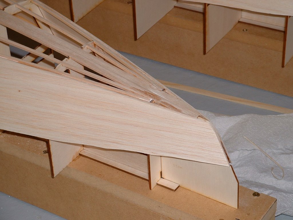
Sailing Model, AMYA Star45 Class | planking sides
Photo showing adding the side planking and sanding to get ready for bottom planking.
He used 1/16" balsa for my hulls since he will be covering it with glass.
It probably will work the same if you are using harder woods, but you will probably want to trace the outline onto the wood and cut close to shape before gluing it on.
Photo showing side plank after being glued on. John used thin ca and glued the 4" wide plank on.
Make sure it is located correctly before starting gluing.
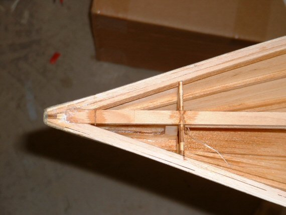
Photo showing the planks after being trimmed close to the stringers.
John used a # 11 Exacto to trim the balsa planks.
Go slow and take multiple passes here. You don't want to remove too much material or you will get a gap when the bottom is planked. Also trim the rails close at this point.
The rails/side joint will be finished once the hull is taken off the board.
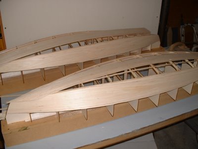
Photo showing the close stringer sanded to fit the side and the back stringer still need to be sanded.
John used a sanding block and sand the sides to match the bottom curve. Balsa sands really easy so this is pretty quick. He used 220 grit paper
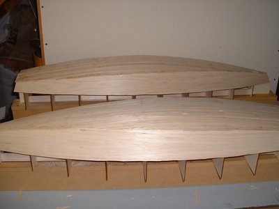
Photo showing both hulls with sides matching the bottom curve and ready for planking.
Photo showing the bow sections after sanding and ready for bottom planking.
==
http://groups.yahoo.com/group/Star45/ for discussions with other Star 45 sailors.
He used 1/16" balsa for my hulls since he will be covering it with glass.
It probably will work the same if you are using harder woods, but you will probably want to trace the outline onto the wood and cut close to shape before gluing it on.
Photo showing side plank after being glued on. John used thin ca and glued the 4" wide plank on.
Make sure it is located correctly before starting gluing.
Photo showing the planks after being trimmed close to the stringers.
John used a # 11 Exacto to trim the balsa planks.
Go slow and take multiple passes here. You don't want to remove too much material or you will get a gap when the bottom is planked. Also trim the rails close at this point.
The rails/side joint will be finished once the hull is taken off the board.
Photo showing the close stringer sanded to fit the side and the back stringer still need to be sanded.
John used a sanding block and sand the sides to match the bottom curve. Balsa sands really easy so this is pretty quick. He used 220 grit paper
Photo showing both hulls with sides matching the bottom curve and ready for planking.
Photo showing the bow sections after sanding and ready for bottom planking.
==
http://groups.yahoo.com/group/Star45/ for discussions with other Star 45 sailors.
Sailing Model, AMYA Star45 Class | building rudder
Here are some photo's showing one way to build a rudder quickly and easily. The quick overview is cut out the shape in a thin material, tape the sides together, insert the rudder shaft, fill the inside of the rudder with epoxy. This takes about 10 min or so to do. Followed by installation in your boat.
John Fisher
Lay out the rudder shape on a sheet of 1/64 ply. On other class boats John used a single layer of a 6 oz carbon fiber layup, so you could also lay up some fiberglass for use on the star. To do a glass layup, just take a sheet of 6 oz or heavier fiberglass, a sheet of lexan or plexiglass, and some resin. The first step is to spread resin on the plexiglass, then apply the fiberglass and then make sure it is all wetted out. Once cure flex the plexiglass and the layup will pop off.
Shows the two sides cut out of plywood, these could be fiberglass instead. Straight sided shapes like shown and the star plans are easier to make.
Tape the two sides together with masking tape. With curved shapes He taped them together then insert the shaft and resin. If you use straight sides on the rudder you can tape one side and then open it up like a book, apply resin, then close and tape shut. The open book method uses less resin but only works with sq or straight sided shapes.
Note the bend John put in the shaft to prevent it from turning inside the rudder.
Shows the top open to pour in resin. John uses a syringe to pour in resin once the shaft is in place. You can add micro balloons to the resin if concerned about weight.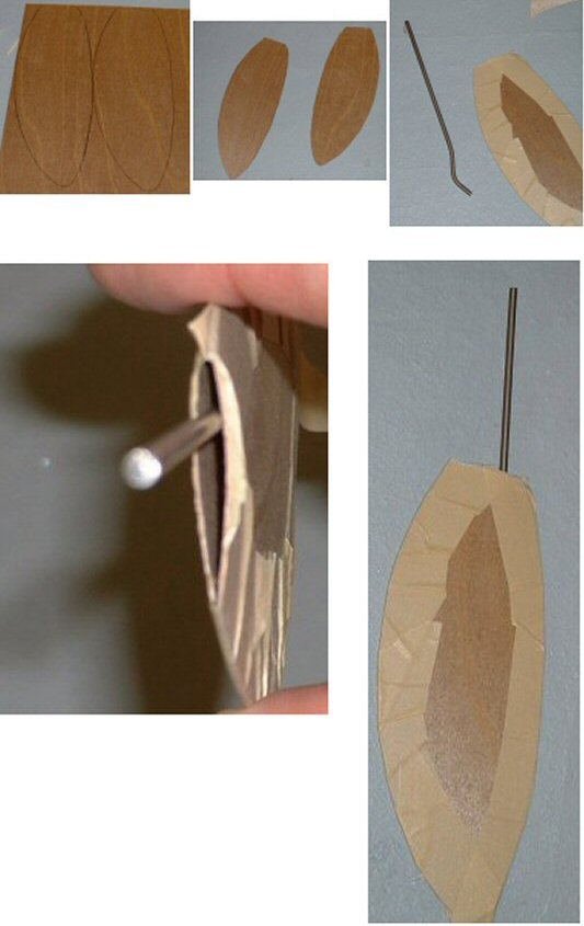
Installing Rudder in Star 45


John Fisher photographer
downloadable files for cutting laser shadows (aka, frames, bulkheads)
Here is another set of downloadable files for Star 45 shadows (aka templates, bulkheads). They reside on my site: http://www.mainzone.com/star45frames/.
You can use your browser, go to www.mainzone.com/star45frames/ select the files you want and they will download to your machine. BTW, only the single stringer files are available from Mainzone.com/.
--
John Fisher provided the CAD files for laser cutting frames. These frames are trimmed based on 1/16 thick planking.
Contact John Fisher to obtain custom DXF and PDF files and to report any issues with the files. email John racer577 at citystar.com (remove the space between 7 and at, change at to @, and remove the space between at and citystar)
--
Most laser plotters used to cut materials require either DXF files or DWG files
DXF files are CAD vector data - plotter files that instruct a device to "start here" then put the (pen, knife) down and "move to, go to"...
Select dxf or dwg based the file type used by your laser cutter.
A CAD viewer or CAD application is required to view the contents. When you download some file types you may see "words" not pictures since these are files with machine commands.
5/02/2011
John Fisher - Dave Mainwaring Award
Star 45 R/C Model Sail Boat - Builders Journal: Star45 : John Fisher - Dave Mainwaring Award
Monday, June 23, 2008
Star45 : John Fisher - Dave Mainwaring Award
Star45 : Message: John Fisher - Dave Mainwaring Award:
"I have received a wooden plaque with a half model of a Star 45 and several brass plates on it from Robert Fisher. Here is what he wrote along with the plaque:
Deed of Gift
John Fisher - Dave Mainwaring Award
The purpose of this award is to recognize the efforts of John Fisher and Dave Mainwaring to utilize 21st Century computer technology to support and facilitate the scratch building for the Star 45 Class, and to regonoize the best builder-sailor at the Star 45 National Championship Regatta. Only people who scratch - built the Star 45 they sail in the National Championship Regatta may compete for this trophy. Any person who did not personally scratch - build the boat they sail is not eligible for this award. The trophy is to be awarded, until the next National Championship, to the eligible person who has the best finish in the Star 45 National Championship. This award shall not be retired.
This award is in addition to the Julie Ayers award!
Don Keeney
Star 45
Class Secretary"
Subscribe to:
Posts (Atom)