Search This Blog

11/08/2015

The Star 45 is a one design class of model yachts

PondYachtworks in Scottsdale, AZ.
American Model Yachting Association Star 45 Class

The Star 45 is a one design class of model yachts recognized by the American Model Yacht Association. This boat is 45" long with a minumum weight of 12 pounds. The design is a semiscale model of a International Star. These boats can be scratchbuilt, from a kit or purchased complete.


11/07/2015


Dave Mainwaring's Friendship Sloop, built Jan 1950 on left, Dave's 42 inch lobster boat on right 2000399
Posted by Hello

What is a hull ? and construction categories

Dave Mainwaring's definitions

HULL defintion of:
The outer shell, including frames, ribs, interior bulkheads, exclusive of masts, rigging, deck and equipment.


"bare hull" defintion of:
A model boat's outer shell, EXCLUDING, ribs, interior bulkheads, exclusive of masts, rigging, deck and equipment. Example. A fiberglass hull as pulled from a mold.

--

A wooden hull:
one constructed of wood (including plywood).


--
A glass hull:
one constructed of reinforced plastic (cloth impregnated with resin). Nominally referred to as a fiberglass hull.

--
A composite hull:
a hull constructed of wood and covered with reinforced plastic (cloth impregnated with resin).
OR:
a hull constructed using a laminate (sandwich) consisting of reinforced plastic (cloth impregnated with resin) on two sides of a core . Core materials may be foam or wood.

Steps toward building a sailing model


Building Displaying Sailing
Model Boats and Ships


So you want to build a sailing model
Find plans for a sailing model, buy or find on-line.

Join a model boat forum for advice.

Buy or borrow books on boat building.

Decide on type of planking and wood to be used to build the model.

Set aside a work space for building.

Review the bill of materials need to build the model and buy the materials.

Order deck and mast fittings.

Order mast (if you are buying the mast) and order sails (or sail material).

Choose the radio system, buy a sail control unit, Order keel bulb or get advice and discuss issues of building your own.

While the hull is under construction build:

Keel fin and ballast bulb

Rudder assembly

Make or assemble spars ( mast and booms)

Build cradle to hold boat under construction and when finished.

Test Radio System and sail control unit

After hull is planked:

Install keel trunk or make provisions for mounting keel.

Install radio and sail control unit, Then remove while construction continues.

Construct deck and hatches

Install/mount deck fittings

Test access to radio and sail control inside the hull.

Provide a exit guide for radio antenna so it can be attached to mast or stays.

Install power switch for turning off batteries

Test mount keel

Paint hull, rudder and keel

Assemble hull, rudder and keel

Set up mast and boom.

Install radio controls.

Check running rigging.

Attach Sails

dry sail model

--

Sail
Display
Storage

11/06/2015

Star construction examples.

PondYachtworks in Scottsdale, AZ.
The Star 45 is a one design class of model yachts recognized by the American Model Yacht Association. This boat is 45" long with a minumum weight of 12 pounds. The design is a semiscale model of a International Star. These boats can be scratchbuilt, from a kit or purchased complete.


S45 Construction planking the bottom

Photograph by John Fisher


Photograph by John Fisher


Since it was requested here are a couple of photo's of planking the
bottom of my two wood/glass stars. photo 01 is the bottom of the first
star about half way done. Planks are 1/16 X 3/8 balsa. These were cut
from a 48" long sheet. Weigh your balsa before buying it. I would not
use a 3 X 48 sheet that weighed in at more than 22g. It takes 3 sheets
to cover the bottom and you could add another 1 to 1.5 oz by using
heavy balsa.
I started in the middle and worked to the outside. I sprayed the
shadows with kicker, then put down a plank, then added super fast CA to
hold it down. If the kicker was not dry enough it would cure before it
wicked into the joint which would cause the next plank to not fit
correctly. I had some variation in the planks, but once they were
glassed the bottom smoothed out quite a bit.
If I were to do another one I would add the half frames. I will be
adding them to the DXF files in the next couple of days for anyone
wishing to cut a set.
Picture shows the bottom after it was completely planked. On the
second boat I got a nice pattern on the bottom since the balsa sheets
had different grain structure. I sanded the sided flush and got the
bottom relatively smooth, but not perfect. With the balsa planks they
were flexible and if sanded too much you get thin spots at the frames.
The glass smoothed out inperfections. If doing a hard wood bottom the
planks should fit better than what I did with the balsa.

====

From: "John Fisher"
Subject: Photo's of star 45 double diagonal planked

Here are some photo's of Sherwood Jones Star 45 with double diagonal bottom planking. He used two layers of 1/16 planking. The planks are 1" wide. He then covered it with 1 ½oz glass. Weight is about the same as mine with the 1/16 longitudinal planks and two layers of 3.2 oz glass. Just goes to show that there are multiple ways to solve a problem.


[Star45] Update on planking bottom with edge glueing.

[Star45] Update on planking bottom with edge glueing.

John Fisher is ready { 4/19/2007 } to glass his latest boat and is sharing how he planked it. His dad built a ply sided, cedar planked star using titebond II and it came out pretty light and stiff. With this information I started to build another hull using the same materials. He felt that edge gluing the planks added a lot of the strength to his boat. John didn't want to glue in extra wood to hold the pins to keep the planks in place for the glue to dry, so I combined two methods of planking. John liked the quickness of planking with CA and kicker, but it lacked stiffness when sanding the bottom before glassing. So he decided to edge glue the planks and then tack them in place to the frames with CA.

In this photo you can see where John put drops of CA on the planks. The wood is slightly darker.


It worked well. John has an edge glued bottom and he was able to plank it in one evening. To do this John first spray the frames with kicker, then apply titebond III to the edge of the planks. He then would hold the plank in place, tight against the previous plank, and apply a drop of CA to each frame to hold it in place. It did not matter where John started, bow, stern, or middle, but do make sure the CA has set up before moving to the next frame. Once the whole plank was in place he came back and wiped off the extra titebond. To fair the bottom to the sides he used a $10, 6" plane from home depot set at .010" depth of cut. It quickly removed the cedar and a little sanding finished the job.

John had one plank that was too thin that he had to remove, it was harder than expected. He had the use quite a bit of force to break the glue joint at each frame, so he is confident that this method is strong. John will also use this for balsa planked bottoms.

In photo # 10 you can see the stern still needs to be trimmed and sanded. John will probably use a saw to trim in close and then sand to fair it.

Hull Templates - bulkheads for building model sailboat, S45


The grid shown is set to 1/4 inch squares. So if you print the templates you can check the size by making sure the grid yields a 1/4 square.

Modelers will use different building materials for the model.These are JPG drawing and print outs may require adjustments to get the widths to correct sizing. For a Star45 AMYA class you need to make adjustments to allow for planking thickness. The rules establish the maximum allowable beam dimension and hull length.

Most browsers will allow you to right click and open the jpg files. You can then save them to your machine.

This set of templates are based on drawing from John Fisher back around August 2006. John may have new and updated drawings available. Check with http://groups.yahoo.com/search?query=star45 membership required.

If you want to scale to use for different model you can change the print out to give you a different grid size.

I want to thank J. Herrmann, www.graphicLanguageOnline.com, for his assistance in converting pdf's to jpg drawing, adding color to the templates and adding the grid to the final images.Rudder templates for a Star45 Class sailing model.The grid shown is set for 1/4 inch squares. So if you print the templates you can check the size by making sure the grid yields a 1/4 inch square.

This set of templates are based on drawing from John Fisher. John may have new and updated drawings available. Check with http://groups.yahoo.com/search?query=star45 membership required.

I want to thank J. Herrmann, www.graphicLanguageOnline.com, for his assistance in converting pdf's to jpg drawing, adding color to the templates and adding the grid to the final images.


These are half shadow that ar eplaced between the templates to add strength to the hull.

Rudder templates for a Star45 Class sailing model


Rudder templates for a Star45 Class sailing model.The grid shown is set for 1/4 inch squares. So if you print the templates you can check the size by making sure the grid yields a 1/4 inch square.

This set of templates are based on drawing from John Fisher. John may have new and updated drawings available. Check with http://groups.yahoo.com/search?query=star45 membership required.

I want to thank J. Herrmann, www.graphicLanguageOnline.com, for his assistance in converting pdf's to jpg drawing, adding color to the templates and adding the grid to the final images.

Star 45 Model Sailboat, (dfx) - HULL, templates. shadows, bulkheads cut files

To model builders: Here downloadable files for Star 45 shadows (aka templates, bulkheads). They reside on my site: www.mainzone.com.You can use your browser, go to the http given and they will download to your machine.

There are two sets.
John wrote:
"one for 2 1/8X 1/8 stringers at the chine and one with 1/4" sq stock at the chine. The SS at the end of the file signifies the single chine stringer. Both use the same building board. Note that the building board is cut for 1/8" lite ply which actually runs about .110" thick."

"Also note that these files do not have "holds" added and are not optimized for cutting. ie I did not make all the line segments poly lines. These should make no difference as long as you are not cutting a lot of sets. The poly lines make about 1 min difference in cutting all 3 sheets."

DXF and PDF files provided by: John racer577 at citystar.com August 06, 2006

--

Most laser plotters used to cut materials require DFX files

DXF files are CAD vector data - plotter files that instruct a device to "start here" then put the (pen, knife) down and "move to, go to"...

----------------------------------------------------------
You can download dxf file. A CAD viewer or CAD application is required to view the contents.

http://www.mainzone.com/s45/star_45_cut_1.dxf

http://www.mainzone.com/s45/star_45_cut_1_ss.dxf

http://www.mainzone.com/s45/star_45_cut_2_ss.dxf

http://www.mainzone.com/s45/star_45_cut_2.dxf

http://www.mainzone.com/s45/star_45_cut_3.dxf

http://www.mainzone.com/s45/star_45_cut_3_ss.dxf

http://www.mainzone.com/s45/star_45_bb.dxf

.............................................

Here areas PDF formated files (converted DFX files).
The PDF's show what is on each sheet, but they are not to scale.

http://www.mainzone.com/s45/star_45_bb.pdf

http://www.mainzone.com/s45/star_45_cut.pdf

http://www.mainzone.com/s45/star_45_cut_ss.pdf

http://www.mainzone.com/s45/star_45_bb.pdf

--
Here are the laser cut shadows laid out on 8.5X11 sheets. These can be used for scratch building. I have included both the single stringer and dual stringer versions. If you use them please make sure and turn off the scale to fit function in acrobat. IF you dont they will print at 94% of correct size.
John

http://www.mainzone.com/s45/star_45_pdf_laser.pdf

http://www.mainzone.com/s45/star_45_pdf_laser_ss.pdf

.............

Here JPG files of the contents from within the PDF.
The jpg files are pictures of each sheet, but they are not to scale.

(The cut.pdf contains three files)
(The cut_ss.pdf contains three files)

http://www.mainzone.com/s45/star_45_bb.jpg

http://www.mainzone.com/s45/star_45_cut1.jpg

http://www.mainzone.com/s45/star_45_cut2.jpg

http://www.mainzone.com/s45/star_45_cut3.jpg

http://www.mainzone.com/s45/star_45_cut_ss1.jpg

http://www.mainzone.com/s45/star_45_cut_ss2.jpg

http://www.mainzone.com/s45/star_45_cut_ss3.jpg


www.mainzone.com/s45/star_45_cut_ss2.jpg

http://www.mainzone.com/s45/star_45_cut1.jpg

http://www.mainzone.com/s45/star_45_cut3.jpg

http://www.mainzone.com/s45/star_45_bb.jpg

star 45 construction | double diagonal planked hull

Model Sail Boat Building, How To Build A Wooden Star45 R/C Sailing Model
star 45 construction | double diagonal planked hull
From: "John Fisher"

Here are some photo's of Sherwood Jones Star 45 with double diagonal bottom planking. He used two layers of 1/16 planking. The planks are 1" wide. He then covered it with 1 ½oz glass. Weight is about the same as mine with the 1/16 longitudinal planks and two layers of 3.2 oz glass. Just goes to show that there are multiple ways to solve a problem.
John

Star 45 Model Sailboat, HULL, ss files - templates. shadows, bulkheads

To model builders: Here downloadable files for Star 45 shadows (aka templates, bulkheads). They reside on my site: http://www.mainzone.com/star45frames/.You can use your browser, go to www.mainzone.com/star45frames/ select the files you want and they will download to your machine. BTW, only the single stringer files are available from Mainzone.com/.

John has two sets available. Mainzone has the ones for a single chine stringer.
John wrote:
"one for 2 1/8X 1/8 stringers at the chine and one with 1/4" sq stock at the chine. The SS at the end of the file signifies the single chine stringer. Both use the same building board. Note that the building board is cut for 1/8" lite ply which actually runs about .110" thick."


DXF and PDF files provided by:John racer577 at citystar.com August 06, 2006

--

Most laser plotters used to cut materials require DFX files

DXF files are CAD vector data - plotter files that instruct a device to "start here" then put the (pen, knife) down and "move to, go to"...

----------------------------------------------------------

Short video about building wooden Star45


The Star 45 R/C Model Sail Boat - Builders Journal

Short video about building wooden Star45 radio controlled sailing model

It takes a minute for video to load from external feed.

S45 Frames (aka bulkheads, shadows) on Mainzone.com

Every man, woman and child should enjoy the pleasure of building a wooden boat

The MainZone web page contains links to downloadable files for use in building the Star 45

This model is is built using frames otherwise known as shadows or bulkheads. The files for these frames reside on www.mainzone.com.


S45 Construction templates for laminating rudder


Rudder templates for a Star45 Class sailing model.The grid shown is set for 1/4 inch squares. So if you print the templates you can check the size by making sure the grid yields a 1/4 inch square.

This set of templates are based on drawing from John Fisher. John may have new and updated drawings available. Check with http://groups.yahoo.com/search?query=star45 membership required.

I want to thank J. Herrmann, www.graphicLanguageOnline.com, for his assistance in converting pdf's to jpg drawing, adding color to the templates and adding the grid to the final images.

RE: slots in (laser cut) frames and stringer from old forum notes 8.31.2010

Ray wrote: >
need to know what are the vertical > slot in frames 4,5,and 6 for also what size stringer goes into frames right > at the bottom where the bottom of hull meets the side of the boat also there > seems too be a slot for another brace on frames 4,5,and 6 directly under the > vertical slots.
Thanks Ray from Down Under

the vertical slots are for the radio tray if you use it. the extra vertical slots by the king plank are just extra strength for the keel area. Chines are 1/4" X 1/4" or 6.4mm sq.

John On 8/30/10,

S45 Construction - completed hull


From: "Daniel Denson"
To: "Dave Mainwaring"
Subject: star45 photos
Date: Sun, 11 Feb 2007 20:01:39 -0600


S45 Construction - fore and aft views of the hull beside the building board.


From: "Daniel Denson"
To: "Dave Mainwaring"
Subject: star45 photos
Date: Sun, 11 Feb 2007 20:01:39 -0600

Hi, Dave
Here are some pictures I took yesterday of my glassed hull plus some commentary:

Pictures #1 & #2 are fore and aft views of the hull beside the building board. I used hardwood plywood with MDF cleats biscuit joined at the edges to keep it flat. Afterward, the whole thing was run over a jointer to make it perfectly flat.

Unfortunately, I wasn't quite as careful gluing on the balsa spacing strips. Although a straightedge was used, the balsa bent away from the straightedge a fraction around form #8. This could have been avoided if the spacing strips were plywood (or I was not a klutz).

Another goof was waiting too long to put on the stringers. After 4 days on the board in Houston humidity, the forms all warped noticeably. Even the transom was crooked. I actually had to use the stringers to align the frames! Don't do this.

S45 Construction -- the stern


From: "Daniel Denson"
To: "Dave Mainwaring"
Subject: star45 photos
Date: Sun, 11 Feb 2007 20:01:39 -0600


Star 45 Hull, -- BOW


From: "Daniel Denson"
To: "Dave Mainwaring"
Date: Sun, 11 Feb 2007 20:01:39 -0600


star 45 construction | double diagonal planked hull


From: "John Fisher"

Here are some photo's of Sherwood Jones Star 45 with double diagonal bottom planking. He used two layers of 1/16 planking. The planks are 1" wide. He then covered it with 1 ½oz glass. Weight is about the same as mine with the 1/16 longitudinal planks and two layers of 3.2 oz glass. Just goes to show that there are multiple ways to solve a problem.


John

11/04/2015

Curved mast -- tuning a mainsail

From: Philgeren@aol.com
Sender: Star45@yahoogroups.com
Date: Wed, 22 Nov 2006 06:58:53 EST
Subject: Re: [Star45] Curved mast -- advantage ??


Curving a mast so that it bends convex forward (concave aft) moves the luff edge of the sail forward and reduces the camber of the sail in the section where the mast is bent (if bent half way up the mast, the camber in the up/down center of the luff of the sail is reduced). In a blow, this reduces power, reduces leeway force, reduces weather helm, allows the boat to increase its speed.

Generally, the minimum position of mast bend is considered to be a curve equal to the luff curve designed into the luff edge of the mainsail. For very light air and for heavy air, maximum mast bend is used for maximum speed. For very light air, less camber makes it easier for air to stay attached to the leeward surface of the mainsail as the air passes aft. For medium air and for waves, where maximum power equates to maximum speed, minimum mast bend is used to get maximum designed camber.


By use of all the tuning controls on a mainsail, one can obtain a certain amount of control over the distribution of camber over the length of the mast, and there will be an optimum camber distribution for any particular sail and set of wind conditions. Pretty complicated to get it perfect, however outstanding sailors like Stuart Walker are on record as saying it is of paramount importance to use this against competitors who are using it. Otherwise, in a one-design competition they win.
My two cents.

S45 Mast and boom

11/01/2015

Lester Gilbert on Sail twist:


http://www.onemetre.net/Design/Twist/twist.htm

Given a wind gradient, and given the way the jib deflects the wind over the main to put it into a header, what sort of twist needs to be applied to the sails to optimise their entry angles?

I've come up with a second twist spreadsheet (about 27kb), which takes the earlier "gradient" and "apparent wind" spreadsheets and combines them with new material on "equivalent angle of attack" of arc-section plates, and on downwash. It's pretty! If you'd like to continue, I'd suggest printing this page, then downloading and running the spreadsheet. You'll need to cross-reference quite often.

UPDATE: A fourth version of the spreadsheet, now twist & downwash, here.

The first part of the spreadsheet allows you to specify the sailing conditions (wind strength, wave size, bearing, boat speed -- see the wind gradient and apparent wind pages for more details) and your boat setup (sail chords, draft, max draft location -- see the entry and exit page for more details). Then the interesting stuff begins.

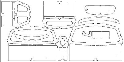
We can start by noting that the red lines represent the "entry" angle of the luff to the wind, and the blue lines represent the "exit" angles. If we assume our sails have an arc-of-circle cross-section (yeah, I know, not a wonderful assumption, but it'll do to highlight the main points), then the entry and exit angles for a sail with max draft at 50% of chord are the same and are equal to 4*ArcTan(draft%). If the sail has max draft at another location, my spreadsheet breaks the arc down into two circular part-arcs, a forward part and an aft part, and calculates from there.

Now, the key at this point is that if these sails were rigid and were sailing off the left hand side of the page, they would generate a fair amount of lift, even though their angle of attack, measured at their chord, is zero degrees. I took a couple of interesting days digging through the NACA archives and I was rewarded with grand-daddy Prandtl (references in the spreadsheet) telling me that these sails develop the same amount of lift as a flat plate inclined at a tangent to the three-quarter chord. Now the tangent at three-quarter chord is none other than the line connecting the leech with the point of maximum draft, as illustrated by the green lines.

Entry, exit, attack for 10% draft Entry, exit, attack for 5% draft

Our 10% draft sail with max draft at 50% is running at an "equivalent" angle of attack of about 11.5 degrees. Move max draft forward some, to 40% say, and the "equivalent" angle of attack reduces slightly to about 9.5 degrees. Another way to look at these numbers is to say that the angle of attack of zero lift, which we'll need in a little while, is -11.5 and -9.5 degrees respectively. Of course, our sails get nowhere near negative angles of attack, they just luff out, but the general idea applies just as long as they are filled and driving. Here is another set of diagrams, but with a 5% draft sail.

Very roughly, take half the draft, and you end up taking pretty much half of all the other figures as well: entry, exit, and "equivalent" angle of attack/angle of attack at zero lift.

(As an aside, the NACA archive was fascinating. In about 15 years from 1905, ie from the Wright brothers, pretty much the whole of aeronautics had in principle been cracked. Prandtl could write a report in 1921 to which the rest of this century really just added footnotes. Amazing. Now we've been sailing for thousands of years, and there is nothing remotely comparable. Great! There is so much yet to know!)

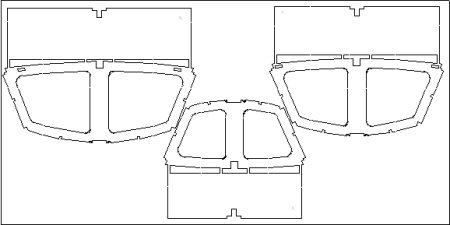
OK. Now it's time to set our sail as a jib. We'll sheet it at 15 degrees to an apparent wind about 30 degrees off the bows, pretty much a standard sheeting angle for an IOM. The 10% draft sail illustrated (which has max draft at 40% of chord) seems to be unhappy at this sheeting angle. While it is making an acceptable "equivalent" angle of attack of about 22.5 degrees to the apparent wind, it is showing a very poor entry angle of around -13 degrees, and really could not hold this point of sailing at all. She'd luff and the boat would have to bear off. Also the exit angle shows the leech somewhat hooked over the centre line.

The 5% draft sail is showing a much better time of it, and can clearly point in the situation we are analysing. The "equivalent" angle of attack is less at about 17.5 degrees, and so the sail will develop less lift than the 10% draft, but the entry angle is nearly perfect -- exactly into the wind -- and the exit angle is good as well, just off the centre line.

Jib Main

So our 5% draft sail seems to be able to point 10 to 15 degrees higher than our 10% draft sail. But you knew that a flatter sail could point higher, didn't you? (In fact, the 5% sail can only point about 3 to 5 degrees higher than the 10% sail, not quite the full 10 or 15 we might have imagined. I'm still working on the reasons for this...) The old salts will tell us that a flat sail doesn't develop as much power, and they'd be right I guess. The maximum coefficient of lift of the 5% sail is about 1.1 at a nominal angle of attack of, say, 11 degrees to the apparent wind, while for the 10% sail it is more like 1.5 at an nominal angle of attack of about 15 degrees. The power developed by a sail is pretty much a direct function of its angle of attack (assuming, of course, the sail hasn't luffed or stalled). In a very real sense, the "only" purpose of a nicely shaped aerofoil (ie a sail) is to allow that aerofoil to achieve a maximum angle of attack. The "only" reason a flat plate isn't a wonderful sail is that it can't achieve much of a useful angle of attack. The 10% draft sail gives us about another 4 degrees of angle of attack over the 5% sail before she stalls, and hence gives us more power, but at the expense of not being able to point as high. On the reach, I'll take the 10% sail please. On the beat, though, pointing ability is more important, so give me the 5% sail.

We are not knocking 10% draft sails. We are just showing how the analysis so far, particularly from looking at the entry angle, indicates they can't point. I sailed a regatta a few years ago with a dog of a boat, and amazingly did well. The reason, I now realise, is that the course was a long rectangle, laid across the wind, so there was only one short beat but two long reaches. What I lost on the beat through lack of pointing I more than made up on the reach with a very full sail set.

Downwash

The next thing to do is to look at the situation with our mainsail. Before we do that, though, we have to remember that it is the downwash off the jib that puts the main into a header, and allows the main to be sheeted more closely to the centre line. So exactly how much is this downwash?

Another trip through the NACA archives revealed another grand-daddy, Munk (reference in spreadsheet), who trailed streamers behind a wing in a wind tunnel and measured the downwash. Thankfully, he wasn't shy about saying straight out that, over the centre section of the wing (we know vortices twirl up at the ends and mess things up there), downwash was pretty much the angle of attack divided by 1.8. Excellent. (If you've ever read any of these NACA reports, you'll know they are stuffed with the most excruciatingly difficult mathematics, whose real-world application to the job at hand is often dismissed with a wave of the hand and "It's obvious that..."!) Our jib at an "equivalent" angle of attack of 22 or so degrees to the wind will generate about 12 degrees of downwash. The main is now sailing into an apparent wind, 30 degrees at the jib, now deflected to about 18 degrees to the centre line. This was why we had to get straight about the "equivalent" angle of attack, because downwash starts much sooner that that indicated by using the boom or chord as the measure of angle of attack. It starts from the angle of "zero lift", which for our sails is (theoretically) something like -10 or -11 degrees.

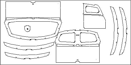
We'll sheet our main at 5 degrees off the centre line, again a pretty standard setting for an IOM. Given that we now realise we are making our boat point high if not actually pinch, we can see how the 5% draft sail again handles the job rather nicely. The entry angle is pretty much bang into wind, and there is a good "equivalent" angle of attack of 19.5 degrees. Interestingly, the leech seems a little hooked, but according to the current analysis that's actually just fine.

Lift coeff distribution

So far, we have been taking a 2D sectional view of our sails. To progress, we now have to apply these ideas to the sails in 3D. The next step is to ask how the downwash is distributed across our jib. It is good to know what it is in the middle -- Munk told us about 0.56 times "effective" angle of attack -- but it is also pretty important to know what it is at the foot and at the head.

The graphs are what Tom Speer's VORTEX95 spreadsheet told me. I still don't fully understand the spreadsheet, but I think it is saying that downwash picks up from the foot and increases towards the head for a triangular sail, and it isn't nicely constant like Munk found with his better-behaved wings. Well, that's what I've taken it to say, so in my spreadsheet I've taken some points off the graph which correspond to the batten positions on the jib and main, to represent the downwash being generated at those positions. I wasn't too confident about the values of downwash at the foot, which the graph says are pretty negligible, so I've fudged here a little, and pretty much made the whole downwash distributions linear for the spreadsheet. Hey, the fun of this is, if you don't like my numbers, you get to put your own in.

As an aside, VORTEX95 also gives a very neat picture of the lift distributions for a triangular sail. One graph is the distribution of the lift coefficient -- the measure of how hard the sail is working to produce lift, everything else being equal. Once it has picked itself up from 0 at the foot, it gives a reasonably straight line -- a pretty even distribution of the lift coefficient which, as everyone knows, is what characterises an elliptical wing and must therefore be A Good Thing -- from about one third of luff until it drops away again right at the head.

The last graph shows the actual amount of lift force being produced by the sail, and pretty clearly it is the bottom third of the sail which produces the most force, due of course to there being more sail area down there. If you'd like to reproduce them, these graphs were obtained with VORTEX95 by putting in a triangular planform on the "Analysis" tab, setting the angle of attack at 16, and twisting the head off -8. Now if there is anyone out there who can really explain the downwash distribution to me, I'd be more than very pleased to hear from you...

So, the spreadsheet accounts for the jib downwash acting on the main by assuming that the jib downwash is, first, 0.56 of the jib "equivalent" angle of attack, and then that it is stronger at the head and weaker at the foot according to the points picked off from the theoretical downwash distribution, as per the graph above.

Lift distribution

Finally, we get the point of the exercise: how this affects the twist to put into the jib and main. Twist is needed for two reasons. First, the wind gradient. The spreadsheet estimates this gradient and suggests what values of twist would match it. But second there is the much more vexed question of the induced upwash at the luff (discussed on the circulation page). The luff upwash is really the complement of the sail's downwash. The more lift the sail generates (ie the higher the angle of attack), the stronger the downwash at the leech, but also the stronger the induced upwash at the luff. This is important because the sail will start stalling (starting from the head). As the induced upwash increases, the "effective" angle of attack of the sail increases, unless steps are taken to lower its angle of attack. So the twist we want to put into the sail is to lower its "effective" angle of attack to something "reasonable" so that if it is to stall, it stalls along the whole length of the luff nearly simultaneously. We don't want it to stall at all, of course, so what we are really doing is ensuring maximum drive from the sail over its entire luff by twisting the head off "sufficiently".

The best I could do on my final foray into the NACA archives was to try and make sense of Millikan, who was the only author I could find to talk about "self-induced" downwash (reference in spreadsheet). I'm on very shaky ground here because the formula he offered seems to be clearly in error to me, and so I've taken from him as the fudgiest of fudge factors a simple function of eta, the wing "efficiency". It turns out that this fudge factor is about 0.62 -- take the downwash, multiply by 0.62 or so, and we just might have the induced upwash at the luff. So the spreadsheet calculates the induced upwash as 0.62 of the downwash, and suggests this as the amount of twist that would "accommodate" the induced upwash so the head doesn't stall. All right, it ain't perfick (as Pop Larkin would say) but it'll have to do for now. Don't like it? Pop your own number in there for eta, something between 0 and 1 will do nicely...

(On the side, there is one more thing. We've been talking here as though the sails were bolt upright, but of course they aren't. Start blowing on them, and they'll heel. Oh, they say, that's just lots of dihedral and maybe just a little sweepback, so nothing really changes aerodynamically except that the forces go down in magnitude, and the vortices just slide off the sail head a little more smoothly. I sure hope so.)

So what do you find when you start playing with the spreadsheet? Well, try setting jib and main twists to the recommendations. You'll need to do this for a couple of iterations, because when you enter the "actual" twists, the "accommodating" twists change for induced upwash to reflect the new values. But it soon settles down. You might not like what you see, particularly on entry angles, so it's then time to sheet out or in, close the slot or increase the slot, bear away or point up, change the sail draft or position of max draft, swap to No.2 rig, and all sorts of things. You're off!

As for me, I've now properly understood how changing the sail draft from the foot to the head (ie the broadseaming at the seams) builds twist into a sail that otherwise can't actually have twist sewn "directly" into it.

Next year, I hope to get into biplane theory and nail down the old chestnut -- should the jib sheet out equally to the main on the reach? We're talking about the simultaneous change of stagger, gap, and decalage here; wonderful stuff! (Sneak preview -- results so far suggest the jib does still need to sheet out just a few degrees more than the main, but not a lot...)

2007-08-12

Lester Gilbert on understanding of sail making for model sail boats

Lester Gilbert wrote:
For anyone interested in sailmaking, I've just finished editing Larry Robinson's "Making Model Yacht Sails" (part 1 only) booklet and have published it as an "international" edition. I've done this, not to get rich ('cos this isn't going to happen to either me or Larry or anyone else connected with this enterprise!), but because I've spoken to a lot of sailors who want to make sails but don't know the "right" techniques, and who are being misled by incorrect accounts of how this might be done.


A sail block
(Illustration from Larry Robinson's "Making Model Yacht Sails")

From my understanding of sail making, there are two ideas I want to contradict.

The first idea is that you can make sails by accurately cutting a curve on a panel, and then attaching it (stitching, gluing) to another panel. Well, while you might be able to cut a good curve some of the time, your fingers just don't have laser accuracy in them to stick A to B and you'll hardly ever obtain reproducible or reliable results. (It might be possible to butt-join the curved edge to another curved edge with a little more reliability, but this doesn't yield what the Equipment Rules of Sailing define to be a seam. Such a sail couldn't be used in sanctioned IOM competition, though it would be OK in a development class.)

The second idea is that you can drape your panels over a "camber board" and get a nice shape that way. Well, let me be clear about what I'm knocking here. I take a "camber board" to be a length of curved surface, where the curve is like the surface of a cylinder. In this case, your panelled sail will have exactly the same shape as a single un-panelled sail and, if you wanted a three-dimensional shape, you've wasted your time (though the result certainly looks the part).

Larry's booklet is the only source I know which carefully explains the use and construction of a sail block. I am sure that this is really the only way (in your garage, please, not in some specialist workshop!) to make professional sails, to obtain reliable and reproducible three-dimensional shaping, and to be able to tweak and change your shaping as you learn about the whole business.

(Warning: Y'all should know I have ten thumbs and have never made a sail yet. What I have done carefully is to watch and talk to those who do, both professionally and as home builders, and measure the results. Making Larry's booklet available internationally is my way of telling you what I've learned.)

Bob Wells will be able to ship this within the USA, and I expect that it will also be available from Don Ginthner at GBMY. For worldwide sales, contact SAILSetc. Bob Wells' e-mail is "bob" at "islandinet.com", GBMY is "rcsailing" at "gbmy.com", and SAILSetc can be contacted through "sales" at "sailsetc.com".

I've attempted an analysis of how blocks work on a new page, Sail blocks analysis, and have a new spreadsheet there to help.

©2008 Lester Gilbert

2006-07-11