Thinning West System Epoxy by Brian Knight
http://www.seqair.com/skunkworks/Glues/WestSystem/Thinning/Thinning.html
"This article appeared in the Fall 1999 issue of Epoxyworks, published by Gougeon Brothers, manufacturers of the West System epoxies." Brian Knight thanks Gougeon for permission to publish this in the December 1999 Falco Builders Letter. "
Here are key excerpts for your review and discussion:
"With wood, the best method of thinning epoxy with heat is to warm the wood and have the resin and hardener at room temperature. Mix the components and apply the mixture to the warm wood surface. Remove the heat source just before the epoxy is applied. When the epoxy mixture comes in contact with the warm wood, it gets warm and its viscosity becomes lower. As the temperature of the wood falls, the thin epoxy is drawn in deeply before it begins to gel. By heating the substrate instead of the components, you get the best of both worlds-low viscosity epoxy on the work surface and longer working time in the mixing pot."
Thinning epoxy with solvent
Adding solvent is a quick, simple method of thinning epoxy, but unlike using heat to thin it, the strength and moisture resistance of the cured epoxy are drastically affected. Below are some of the effects adding solvent has on West System epoxy. While there are a large number of chemicals available to thin epoxy, we selected acetone, lacquer thinner and denatured alcohol for this discussion because they are commonly available and do a good job of reducing viscosity. Additionally, these solvents evaporate quickly and are less likely to be trapped in the cured epoxy-an important characteristic. For a variety of reasons, fast evaporating lacquer thinner appears to be more appropriate for thinning purposes than acetone or alcohol.
10/16/2008
10/15/2008
So you want to build a sailing model
Find plans for a sailing model, buy or find on-line.
Join a model boat forum for advice.
Buy or borrow books on boat building.
Decide on type of planking and wood to be used to build the model.
Set aside a work space for building.
Review the bill of materials need to build the model and buy the materials.
Order deck and mast fittings.
Order mast (if you are buying the mast) and order sails (or sail material).
Choose the radio system, buy a sail control unit, Order keel bulb or get advice and discuss issues of building your own.
While the hull is under construction build:
Keel fin and ballast bulb
Rudder assembly
Make or assemble spars ( mast and booms)
Build cradle to hold boat under construction and when finished.
Test Radio System and sail control unit
After hull is planked:
Install keel trunk or make provisions for mounting keel.
Install radio and sail control unit, Then remove while construction continues.
Construct deck and hatches
Install/mount deck fittings
Test access to radio and sail control inside the hull.
Provide a exit guide for radio antenna so it can be attached to mast or stays.
Install power switch for turning off batteries
Test mount keel
Paint hull, rudder and keel
Assemble hull, rudder and keel
Set up mast and boom.
Install radio controls.
Check running rigging.
Attach Sails
dry sail model
--
Sail
Display
Storage
Model Sailboat Plans on line


Most browsers will allow you to right click and open the jpg images. You can then save them to your machine.
This set of plans are based on drawing from John Fisher 2006. John may have new and updated drawings available. Check with http://groups.yahoo.com/search?query=star45 membership required.
I want to thank J. Herrmann, www.graphicLanguageOnline.com, for his assistance in converting pdf's to jpg drawing, adding color to the templates and adding the grid to the final images
You can print these drawing to many different sizes.They are not necessarily to scale.
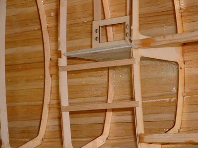
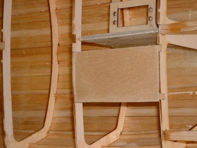
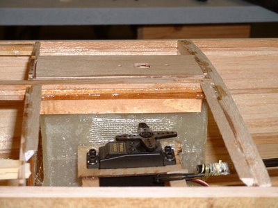
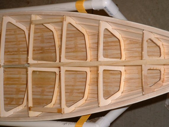
Inside a R/C sailing model hull
John Fisher photographer and builder!
Radio Board stringers between bulkheads
(Note the method of keel support using these stringers)
Radio Board
Rudder Servo
Mast support (inside hull)


Radio Board stringers between bulkheads
(Note the method of keel support using these stringers)

Radio Board

Rudder Servo

Mast support (inside hull)

S45 sail boat Rigging Bill of Material from John Fisher
To:Star45@yahoogroups.com
From: 'J Fisher'jfisher@wildblue.net
Sender: Star45@yahoogroups.com
Date: Wed, 3 Jan 2007 21:02:38 -0700 (Mountain Standard Time)
Subject: Re: [Star45] Deck rigging and such
Here is the list on the star 45 yahoo groups for rigging. I am using the following for my next couple of builds:
GBMY item #, description, qty, purpose
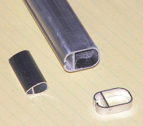
019, 3/8' alloy tube, 1, Jib boom
034, Hales single block, 2, main and jib sheets
146, tapered drain plug, 1, plug in transom
182, Z sheet hook, 2, sheet ends/boom attachment
202, large bowsie, 1, back stay/forestay with 80 lb Dacron, order small ones if using spektra
206, O-rings, 1, hold the Z hooks to the boom.
254, double block, 2, main sheet and jib sheet adjuster
255, sheet exit, 1, turning block for main sheet from under deck to above deck.
269, eye plate, 1, mounting for jib block.
272, 180 deg sheet lead, 1, turn around for jib tweaker
280, sheet hook, 1, hooks for backstay and fore stay.
282, tang, 1, attach lowers to mast.
907, rigging screw, 4 hooks, 2 packs, upper and lowers to the deck.
I also build my own chain plates, so I don't order them from GBMY. Don does carry them if you need them. I also like the Ludwig mast better than the bantock mast, so I ordered 8 foot masts cut to 69' from Larry Ludwig, the other 28' or so is the main boom. Last time I made all my own boom vang, mast fitting. This time I ordered them from Larry. You can use the bantock mast, boom, and fittings from GBMY as well. They are good stuff and I have them on my IOM.
The back stay crane is made from 1/16 (.063') aluminum that I bought at the local hobby shop.
John Fisher
---
From: 'J Fisher'jfisher@wildblue.net
Sender: Star45@yahoogroups.com
Date: Wed, 3 Jan 2007 21:02:38 -0700 (Mountain Standard Time)
Subject: Re: [Star45] Deck rigging and such
Here is the list on the star 45 yahoo groups for rigging. I am using the following for my next couple of builds:
GBMY item #, description, qty, purpose
019, 3/8' alloy tube, 1, Jib boom
034, Hales single block, 2, main and jib sheets
146, tapered drain plug, 1, plug in transom
182, Z sheet hook, 2, sheet ends/boom attachment
202, large bowsie, 1, back stay/forestay with 80 lb Dacron, order small ones if using spektra
206, O-rings, 1, hold the Z hooks to the boom.
254, double block, 2, main sheet and jib sheet adjuster
255, sheet exit, 1, turning block for main sheet from under deck to above deck.
269, eye plate, 1, mounting for jib block.
272, 180 deg sheet lead, 1, turn around for jib tweaker
280, sheet hook, 1, hooks for backstay and fore stay.
282, tang, 1, attach lowers to mast.
907, rigging screw, 4 hooks, 2 packs, upper and lowers to the deck.
I also build my own chain plates, so I don't order them from GBMY. Don does carry them if you need them. I also like the Ludwig mast better than the bantock mast, so I ordered 8 foot masts cut to 69' from Larry Ludwig, the other 28' or so is the main boom. Last time I made all my own boom vang, mast fitting. This time I ordered them from Larry. You can use the bantock mast, boom, and fittings from GBMY as well. They are good stuff and I have them on my IOM.
The back stay crane is made from 1/16 (.063') aluminum that I bought at the local hobby shop.
John Fisher
---

photo's courtesy of "Larry Ludwig" at www.LudwigRCYachts.com, Ludwig Mfg.
Jib Tweakers
Jib tweaker with swing arm sail control unit:

Adding a servo to the end of the jib sheet allows the jib to be "tweaked" by changing the effective length of the sheet while under sail. The challenge is to set the servo to mid point when setting the model up prior to sailing.
Tweaker with drum type sail control unit.

___________________________________
A jib twicher is a rig that pulls the jib boom to port or to starboard when sailing down wind.

These to devices are often confused with each other :)
10/08/2008
The following are a compilation of Lester Gilbert's materials, materials of others"
The Lester Gilbert pages are published with his permission and are "only intended for educational, model building guidance and discussion purposes User beware the writers assume no responsibility for anything. If you'd like to reprint, copy, or link to anything, please attribute words, diagrams, photos, spreadsheets, and software carefully and obtain permissions where appropriate so others know who was the source. The content is a compilation of my materials, materials of others and Lester Gilbert."
Lester Gilbert is at Learning Societies Lab, University of Southampton, Southampton SO17 1BJ, United Kingdom he may be reached by email at lg11@soton.ac

Adjusting the wind tunnel model
Lester Gilbert is at Learning Societies Lab, University of Southampton, Southampton SO17 1BJ, United Kingdom he may be reached by email at lg11@soton.ac

Adjusting the wind tunnel model
Lester Gilbert on RMG Digital Voltage Display
Lester Gilbert Writes:
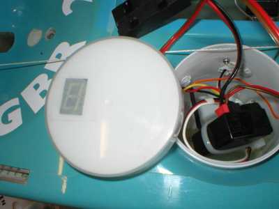
I've acquired one of Rob Guyatt's "flash" units (an RMG Digital Voltage Display) and installed it in the lid of my pot. It works perfectly, and makes for an altogether more relaxed day of sailing.
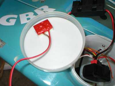
It is quite simple to cut a rectangle into the lining of the SAILSetc pot lid, and then to fasten the flash unit to the inside of the lid with a strip of double-sided sticky-backed tape.
(2006-07-11
©2008 Lester Gilbert
I've acquired one of Rob Guyatt's "flash" units (an RMG Digital Voltage Display) and installed it in the lid of my pot. It works perfectly, and makes for an altogether more relaxed day of sailing.
It is quite simple to cut a rectangle into the lining of the SAILSetc pot lid, and then to fasten the flash unit to the inside of the lid with a strip of double-sided sticky-backed tape.
(2006-07-11
©2008 Lester Gilbert
Lester Gilbert on boat balance
The boat is balanced by either moving the sail plan forward to reduce weather helm/increase lee helm, or moving the sail plan back to reduce lee helm/increase weather helm. Depending upon the mast step you have in your hull, you'll do this by raking the mast (pivoting it on its heel), or moving it fore and aft in a mast slot.
For any given hull/rig combination, Graham Bantock feels the degree of weather helm is dictated by three basic factors:
* mast rake/mast position
* relative twist in main and jib
* relative sheeting angle of main and jib
with the minor factors:
* relative camber of main and jib
* relative shape of main and jib.
He goes on to say:
There is a fairly small range of successful pairings of twist and sheeting angle. The sheeting angle ranges are covered by the range 8 to 15 degrees for the jib, and 2 to 8 degrees for the main. Keep the twist in the sails so they look much the same from astern. Use mast rake/mast position and relative sheet angle to tune the balance. Use sail camber primarily as a throttle - fairly flat in very light airs, fuller as wind speed increases up to the point where you need to keep the boat more upright for best speed and pointing when you flatten sharply. Camber can also be used to adjust the helm of the boat. Experiment.
As far as I can tell, my Ikon and Italiko tune up just like any other IOM, the major issue being to get their balance right -- ie, appropriate weather helm. So far, I've found both work best for me with a touch of weather helm, that is, when they reliably round up into the wind rather than sailing "neutrally" with my finger off the rudder stick. If you have your rudder trim calibrated, I'd suggest going for that amount of mast rake which gives you about 2 or 3 degrees of weather helm as the "ideal".
As an aside, some sailors feel that mast rake does other things for you, perhaps improving the lift characteristics if the mast is raked well back to give some sort of "sweepback". As far as I can see, mast rake in an IOM is exclusively concerned with boat balance and helm, and has negligible other effects on any other characteristics of the boat.
There is an aspect of helm that has puzzled me for quite a while, and that is the phenomenon called "snap" weather helm. This happens when an otherwise well-behaved boat luffs violently into wind when a puff hits, and I had this problem with my Ikon. When I started sailing my Italiko and until recently, I never encountered it, and began thinking that snap weather helm might be a characteristic of hull shape. I realised I was wrong about hull shape when my Italiko snapped back at me, and I spent a little time investigating. It now seems to me that I had inadequate rig tune.
2006-07-11
©2008 Lester Gilbert
Lester Gilbert on winch drum's and winching
I've had two kinds of winch drum turned in my efforts to fine-tune the response of my RMG-380 sail winch at close-hauled. The RMG-380 (and, for the IOM class, the more appropriate RMG-280) has outstanding power and speed. I have my mainsheet post as low down as possible, and deliberately use the power of the RMG to "sheet vang" -- tighten the leech of the main at close-hauled when I want to. Please DON'T try this with a Whirlwind, Futaba, HiTec, or ANY other winch! I also have absolute confidence in the ability of the RMG to sheet in from a broad reach to close-hauled when the wind is right at the top of "A" rig within an instant. In fact, I've broken my servo tray proving it can do this. But the resolution and repeatability of the RMG at just off close-hauled is not wonderful.
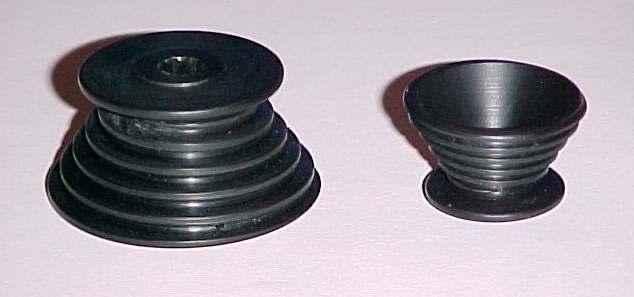
Snail drum
The 8-bit analogue to digital converter of the RMG controller electronics provides for 255 separate positions of the drum over its travel of around 5 revolutions. If we call this a round 250 positions, we get 50 positions per revolution. If the drum diameter is, say, 28mm, then one revolution pays out about 90mm of line, or about 1.8mm per position.
The problem is, although the theoretical resolution is1.8mm, repeatability is about twice this value, around 3.6mm, and at close-hauled 3.6mm is a very significant difference. The winch electronics cannot (at present) do better. So it is necessary to have a drum whose diameter is less at close-hauled. The first picture illustrates two "snail" drums, which have an ever-changing drum "diameter". The larger drum, shown upside-down, has a total travel of about 600mm, and the smaller drum has about 300mm. (You may need to turn up your screen brightness to see the detail clearly. These black, shiny things are very difficult to photograph well.) The smaller drum has a maximum diameter of about 28mm, down to about 12mm close-hauled. One revolution at close-hauled pays out about 40mm, so resolution is about 0.8mm per position, and repeatability is about 1.6mm.
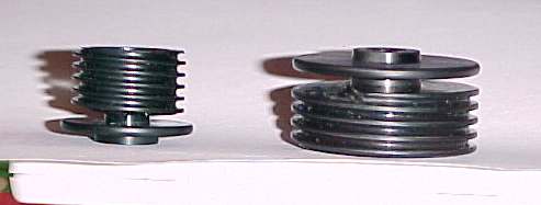
Step-down drums
The second picture illustrates two "step-down" drums. These drums have two diameters, a larger diameter, and a smaller diameter. The larger of the step-down drums illustrated (again, upside-down) has a total travel of about 550mm, through four turns at the 32mm larger diameter, and any remaining turns at the 12mm smaller diameter. For all of these drums, the sheeting line is tied through a small hole in the drum at the fully sheeted-out position, at the largest diameter of the drum just where the channel starts.
Your friendly lathe operator should be able to turn one of these drums for you to try. I understand that it is an exacting and time-consuming process, though, so be sure he owes you a favour first; it would be rather expensive if you were to be charged full commercial rates. Alternatively, Rob Guyatt now sells excellent examples of these drums to suit his RMG winches, in three diameters, at exceptionally good prices. What are you waiting for?
Closed-loop sheeting arrangement
Naturally, neither of these kinds of drum can be used in a "closed-loop" system, but I've not found that to be a drawback. In fact, just the opposite; if the sheeting line is tied to the drum so that it is fully sheeted out on the run with absolutely no more line around the drum, then should the line jump off the drum at any time, sheeting right out and then sheeting back in again always clears the problem. The diagrams illustrate the two main methods of sheeting from the winch drum -- closed-loop or open loop -- and an arrangement of the sheets.
Open loop sheeting arrangement
The "Drums" spreadsheet (about 16kb) makes some simple calculations relating to sheeting and drum turns. Given the main boom sheeting angle and the sheet attachment point, the line run is calculated. Then the number of turns needed for each type of drum to sheet that amount of line is calculated. For a "simple" drum, the number of turns is calculated straightforwardly. For a "snail" and a "step-down" drum, given the maximum and minimum drum diameter, you enter trial values for the number of turns until the calculated wind is about the same as the expected line run. Alternatively, the revised spreadsheet has some macro buttons you can click. (Note that the presence of the macros may trigger an anti-virus alarm in your system.)
Sheeting lines arrangement
A final comment concerns getting to use the small amounts of sheeting required by "sheet vanging". Normally, it would be rather tricky to be able to move the Tx winch stick by, say, 1/50th of its travel, never mind 1/250th, and some skippers wonder whether the fuss with these drums is worth it. I use a Futaba 3VC computer radio (which can command the Rx to 1/1024th of full-scale travel at highest resolution) and have "exponential" travel on the winch stick, such that one "click" on the stick, 1/20th of the stick travel, gives me about 1/150th of travel at the winch. Another click gives me about a further 1/80th of travel at the winch. I thus have three winch settings which I use at close-hauled, corresponding to pinching, normal, and footing, with three different amounts of twist pulled into the mainsail and just a small change in sheeting angle.
2006-07-11
©2008 Lester Gilbert
Lester Gilbert on Boat weight and Boat speed
I was wondering whether it really mattered if a yacht was a little overweight. I've taken the "Acceleration" page spreadsheet and produced a whole new version. It calculates drag and acceleration against a time line, rather than against a speed line (spreadsheet here, approx 96 kb), in order to yield relatively stable calculations. More importantly, it now factors in the yacht displacement in order to calculate acceleration, and calculates the distance travelled during acceleration. For a given wind speed and displacement, the sorts of results it gives are shown below, plotting speed and distance against time while reaching and while running. These particular graphs are for a wind speed of around "1", showing the yacht reaches maximum reaching speed after about "6" units of time. These are arbitrary units, because the spreadsheet is not calibrated. However, if you think "1 metre per second" for the wind speed, and "6 seconds" for the time, you'll not be too far out.
http://www.onemetre.net/Build/Accel/Accel2.htm
http://www.onemetre.net/Build/Accel/Accel2.htm
Subscribe to:
Posts (Atom)