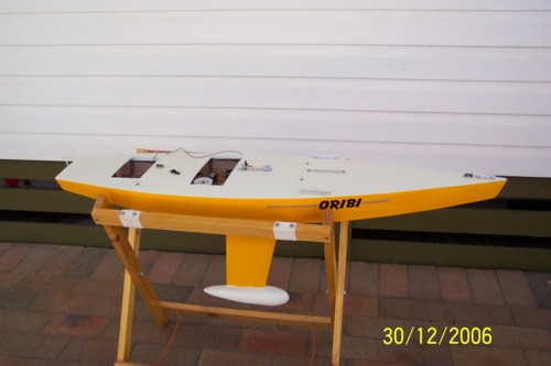
Search This Blog

12/30/2006

12/23/2006

S45 Construction | John Fisher - keel tubes

Date: Fri, 22 Dec 2006 18:22:14 -0700 (Mountain Standard Time)
From: "John Fisher"
To: "Dave mainwaring"
Subject: Star 45 keel tubes


Here is a photo sequence showing how I made my keel tubes. I am using a keel from CPM (David Ramos) with longer keel bolts so they will go through the deck when finished. I coated the brass rod with carnuba was as a mold release.

http://woodstar45.blogspot.com/2006/10/s45-construction-john-fisher-keel.html

John

Radio install on star # 3 | John Fisher

http://woodstar45.blogspot.com/2006/10/s45-model-boat-construction-sail.html

Date: Fri, 22 Dec 2006 18:09:14 -0700 (Mountain Standard Time)
From: "John Fisher"
To: "Dave Mainwaring" ,
Subject: Radio install on star # 3


Here are a couple of photo's of my latest star. I have just finished installing the radio tray for an under deck winch, jib tweaker, and rudder servo. I also included a photo of the sheet through deck mount. I also show the jib tweaker turn around. The part is a 180 deg sheet lead from great basin.

The radio tray is 1/16 ply backed up with 1/8 X 3/8 spruce or basswood. Note the glassing at the ends. This adds a lot of strength to the joint and I highly recommend adding it. I have 1" wide glass tape that I cut in half, then sprayed with 3M77 so it will stay in place for gluing. Then a dab of your favorite epoxy and you are done.

12/21/2006

Duddy's universal building jig,: materials used


From: "MICHAEL DUDDY"
M. Duddy's universal building jig
Date: Thu, 21 Dec 2006 08:28:46 -0500


The material used in the jig is 1"x1"x1/16" aluminum square tube( very ridged and no twist).
The ends are 1 1/2" angle bolted in two places on the ends as you can see in the pictures. I checked the ends with levels and the jig is dead straight.

The angle pieces with the screws in them are 3/4"x 1/16" x 6" long. You mount your frames to these with a square on the centerline of your frame inline with the center of the attachment piece.

Next you use a square to square these on the jig rails, and line up with the string. Now you are rite on brother.:) The dimensions of this jig are ; 60" long x 6" wide because they only had 60" pieces in the rack , and I didn't know what I might be building in the future. You can make it any size you want.

The end plates I made from 1/4"(stuff laying around), and milled slots in them so I could slide the jig to one side or the other for balance. If you have any questions or if I can help you in any way , get in touch with me.

Mike

12/19/2006

S45 Construction Michael Duddy's Universal Building Jig


From: "MICHAEL DUDDY"
Subject: universal building jig
Date: Mon, 18 Dec 2006


Attached is the pictures of the jig. It isn't hard to build , and can be used on most any boat model (maybe even wings too). It is all adjustable , and it can be tilted on either side to plank the sides of the hull you are working on. Once the hull is done it can be removed very easy. The materials are available at places like Home Depot,or Lowes , and I know of some aluminum suppliers that sell in small quantities. I could draw up some plans if anyone is interested. I have to make a stem and transom angle holder for it.


Join the AMYA Star45 Class !

12/17/2006

Tank Notes on International Star Boats (1/3 size models)

Tank Notes on Star Boats: "ROUND chines add another complication to getting speed from a hull. This bad feature is an extension of the range in which burble will appear. In the wake of any transom-sterned boat, a severe agitation of the water may be noticed, an indication that a breakdown is occurring in the flow of water under the boat. When water is released from the transom properly, the burble that means an increase in resistance is not present. However, it is possible to run without burble only above and below definite speeds, the range depending on the lines of the boat. But, also, the shape of the chine has some effect. With a square-chined Star, it is safe to say that the burble will appear at about 5 knots and run clear aft at about 6 1/2 knots (when the boat is upright and on the designed trim). Increasing the bilge radius to 3 inches, on a Star, increases the burble range by dropping the lower limit to 4 1/2 knots and by raising the upper limit to 7 1/2 knots. Also, a model with round chines, when running heeled, begins to climb out of the water forward as the speed increases, the round chine acting as a flat surface on which the model tries to plane. To complete the analysis, it is necessary to go back to sharp-chined heeled models, in which the burble range is from 4 1/2 to 6 1/2 knots.

With the sharp-chined models, there was no indication that the bow tried to rise, a further proof that the sharp entrance angles are imperative. The easiest way to decrease the burble range is to trim the boat by the head and, conversely, the handicap of a trim by the stern is that it will cause the water to break away from the transom at speeds lower than normal. Under all conditions except that of a rounded chine, the burble range increases by dropping the lower limit; the upper limit is quite constant, being 6 1/2 knots. Interestingly, that is approximately the speed at which some styles of Star hulls show the first signs of planing.

In summary, it can be said that many Star boat owners might have had a faster boat than the standard Star because:
1. The fore and aft contour of the boat had been flattened and a large decrease in resistance accrued.
2. The boat was sailed down by the head, at least while running, which would give a 12 per cent decrease in the power required to drive her.
3. Square chines might have been used, which mean a decrease in resistance.

Although this work was done directly on Stars, the information is also applicable to other types of square-chined boats. But it must always be remembered that, even though a skipper have all the information in the world and his boat has an enviable heritage from designer and builder, the combination must sail hard to be a winner."


Complete article on www.starclass.org/

12/05/2006

Star 45 Class | Rod Carr's "SPOT" Star #1


The modern day Star 45 Class got started back "when" Rod Carr got the AMYA launched and introduced the modeling world to his Star #1

11/26/2006

STAR 45 CLASS TECHNICAL COMMITTEE Nov. 2006- Dec. 2007

Phil Geren Sat, 25 Nov 2006 20:57:08 EST

STAR 45 CLASS

TECHNICAL COMMITTEE

November 2006 To December 2007


Table of Contents

Origin of this Committee. 3

Charter 3

Membership. 3

Processes. 4

Action Items, prioritized. 5


Origin of this Committee

Don Keeney, Class Secretary of the Star 45 Class of model yachts sanctioned by the American Model Yachting Association, announced at the National Championship Regatta held in October of 2006 that he plans to assist the Membership of the Class in achieving a clear, unambiguous, and uniform interpretation of the Rules. He also stated a goal to enhance the growth of participation in the Class.

To these ends Don formed the Star 45 Class Technical Committee of November 2006 through December 2007. The objectives, members, working processes, an an initial list of prioritized action items are set forth below.

Charter

The Technical Committee shall:

µ Ensure that the Star 45 Class Rules are:

o Capable of being clearly understood by all Class members without ambiguity;

o Subject to only one interpretation;

o Adequate to preserve the one-design principle of the Class, while allowing room for improvement in sailing performance

By:

o Formulating and publishing Guidelines for Rule Interpretation and Application (“GRI”);

o Submitting to the Class Secretary proposed Rule Amendments and New Rules;

µ Enhance growth in Class Membership by:

o Discovering and publishing corrections and clarifications to errors and ambiguities in the approved Star 45 reference and construction plans;

o Discovering and publishing Guidelines For Building And Tuning (“GBT”) Star 45 Model Yachts in order to assist a builder in achieving a competitive racing boat, at minimum cost, complying with the Rules, regardless whether building from scratch or from kit materials.

Membership

The Technical Committee shall comprise eight participants: the Class Secretary, Committee Chairman, and six Members. The Committee Chairman and the Members shall have voting rights.

The following people shall be directly involved in the business of the Technical Committee:

Class Secretary: shall participate in all discussions; shall take the final decision on all issues regarding the Rules after receiving the recommendation of the Committee. shall have no vote in Committee voting processes; shall, subject to his sole discretion, publish Guidelines for Rule Interpretation and Application received from the Technical Committee; shall, subject to his sole discretion, submit to the Class Membership for approval Rule Amendments and New Rules received from the Technical Committee;

Committee Chairman: shall recruit to fill vacancies on the Committee; shall chair discussions among Committee Members and administer voting processes; shall have voting rights; shall prepare the final wording of GRIs and GBTs based upon the consensus of the Committee; shall publish GBTs;

Committee Members: shall bring issues to the Committee for action; shall discuss and reach consensus, through simple majority vote on all issues; shall formulate Guidelines for Rule Interpretation and Application and submit these to the Committee Chairman for preparation of a final document; shall formulate, prepare, achieve consensus upon and submit to the Committee Chairman Guidelines For Building And Tuning Star 45 Model Yachts.

Present Committee Membership:

Class Secretary: Don Keeney, 1keyknee@281.com

Committee Chairman: Phil Geren, philgeren@aol.com

John Fisher, racer577@citystar.com

Dave Mainwaring, mainwaring@rcn.com

David Ramos, david@rcyachts.com

Peter Latournes, platournes@aol.com

Mel Holman, foxnlox@buckeye-express.com

Region 3 Candidate - being recruited

Processes

µ Discussion shall take place through postings of Email messages to:

star45technicalcommittee@mainzone.com

or messages posted while visiting this website:

http://mainzone.com/cgi/lyris.pl?enjter=star45technicalcommittee .

Posted messages are read at: http://mainzone.com/cgi/lyris.pl?enjter=star45technicalcommittee .

Please note that photos and attachments cannot be sent to the above.

Photos and attachments can be sent to: http://star-45.blogspot.com/ , where building information is being archived.

µ Consensus shall be by simple majority vote;

µ The quorum shall be the Committee Chairman plus 4 or 6 Members;

µ Guidelines for Rule Interpretation and Application shall be published by the Class Secretary as he sees fit;

µ Guidelines For Building And Tuning Star 45 Model Yachts shall be published at Star 45@yahoogroups.com , at star45houston.com , and at http://star-45.blogspot.com/ .

µ Preliminary performance targets for the Committee are to:

§ issue this Technical Committee organizational document for voting by the Committee on 26 November 2006;

§ issue one GRI per month;

§ issue the first GBT within three months.

Action Items, prioritized

1. Guidelines for Rule Interpretation and Application:

a. overhang of backstay chainplate, strut, boomkin or other device – how to measure

b. “hull” definition, wood, fiberglass

c. 1/4” or 3/8” bow bumper overhang

d. rudder profile and dimension limitations

e. jib numbering

f. obtain reference and constructing drawings additionally from Class Secretary (not just Ship’s Store)

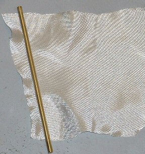
g. fiberglass = fiber reinforced plastic, such as glass or other fiber cloth impregnated with hardened epoxy or polyester resin

h. Rule 1.4: rule to be waived if unable to be reasonably applied, such as, for example, if the deck or keel is attached, if verification by another Class member is inconvenient (requiring mailing the model, for example). Alternatively, Rule 1.4 to be deleted.

i. Hierarchy between Rules and Drawings

2. Guidelines For Building And Tuning Star 45 Model Yachts

a. Make available the best of the versions of the laser-cut frame files with instructions, online

b. Discuss if http://star-45.blogspot.com/ organization is the optimum for guiding beginners

c. Keel and bulb locations

d. Wings on rudders and bulbs

e. Glue recommendations

f. New building materials

g. New sources for woods, other materials

h. Jib tweakers

i. Jib twitchers

j. Drawings, correctd on CD

k. Camber recommendations for keels and rudders

l. Backstay tension calibrated for mast bend

m. Mast bend recommendations vs wind speed vs luff curve

n. Sheeting angles vs windspeed

o. Mast position vs wind speed

11/17/2006

Star 45 Construction ply sides and a cedar strip planked bottom

From: "John Fisher"

Here is my dad putting the sides on his boat. This method could be done with balsa as well if someone has an issue with CA. The clips he uses can be purchased at any office supply store.

His boat is going to have ply sides and a cedar strip planked bottom. I made him a set of frames with 1/16 cut on the sides and 1/8 cut on the bottom for this application.

Using 1/16 inch plywood for sides

I use Titebond glue instead of CA. I first clamp a 4" by 48"
piece of the plywood against the framework on the building board. I then trace around the profile of the side to outline the approximate size and shape of the plank. Using a knife, I cut around the outline to remove excess plywood leaving about a half inch extra. This should be sufficient to allow the clamps to grab the stringers along the rail and the chine. I then apply Titebond on the stringers and clamp the plywood
in place starting in the middle and working to the ends. I used about 40 clamps to ensure a tight seal (2679).

I trim the plywood back to about a 1/16 of an inch above the balsa stringer using a Stanley modeling plane (2681). These cost about $10 at Ace Hardware or any home warehouse. This takes about 5 minutes and then I use sandpaper to finish the trimming.

Star 45 Construction splicing wood to get longer pieces


John Fisher writes:
Since 48 inch balsa is hard to find, I used 1½ pieces of 36 inch balsa that I joined using a 45 degree scarf. I cut a small (about 1 inch long) piece of the balsa I'm joining as a support for the joint, both structural and for alignment. 2668 shows the three pieces before gluing. I use titebond rather than CA because I'm sensitive to CA. I clamp the three pieces as shown in 2669 using the table top and the small piece to gain alignment in both directions for the two long piece. During construction the small piece of balsa must be placed where it doesn't interfere with the construction (2673). Once the stringer is glued to another piece of planking or another stringer the small piece can be removed using an Exacto knife and sandpaper

11/13/2006

S45 Construction radio tray as a built in component to the hull.


From: racer577@citystar.com

I am building a new boat and incorperating a few new ideas. One is to
include the radio tray as a built in component to the hull. I added two
1/16 plywood plates that are notched to fit into the frames. This
particular one is designed to hold one servo and a RMG winch. I will see
how this works out. The down side is going to be limited access, but the
up side is light weight and strength.

If there is interest I may build this up for other winch options.

John

S45 Construction Rigging photos from John Fisher


Subject: Star 45 deck rigging

Here are some rigging photo's. Back stay fitting,
jib lead that I used, note that it holds the line off center so
it doesn't get caught in the mast jack, Another shows the notch I
put in the mast so I could put the sail on and the crane that I used,
and another shows my mast jack and vang. Plus a photo of my deck layout on
812.

John

S45 Construction rudders on #812 and #813


From John Fisher:
Here are the two rudder examples, 812 is the thicker one and 813 is thinner. The % thickness is the same on both, but 812 is thicker over more of the rudder since it was a 1/8" pc of balsa that was rounded on the ends. 813 was made by two pcs of 1/64 ply expanded over a 1/8" shaft.

They clearly show the difference in cross section, however they’re a little small to judge the details. Interested in contrasting the radius of the leading edge. Is there much of a difference between the two rudders in the first .125 to .25 of the foil? Typically sections with a sharp leading edge will lead to a pronounced stall as the flow can’t make the sharp turn to stay attached to the low pressure side.

10/08/2006

Build this fantastic model sail boat!

Build a Model Sailboat !!

The information used for the " Model Sail Boat Building, Making A Wooden Star45 R/C Sailing Model" includes posts found on the companion blog: The Star 45 R/C Model Sail Boat - Builders Journal


"Model Sail Boat Building, Making A Wooden Star45 R/C Sailing Model" is a start to finish, step by step, building manual. Including directions for covering a wooden star with fiberglass.

With the popularity of radio-controlled models, the number of people interested in owning a model yacht has also grown - in geometric range. As with model aircraft, the choice of sailing models runs the gamut from child's toy to sophisticated craft.

Over the past 30 years I have fielded many questions regarding the choices and considerations which go into selecting a radio-controlled sailboat.

Four questions are asked over and over by prospective skippers: How do the radio-controls work? How much do they cost? What do I look for when I buy mine? And, where can I get plans and instructions for building a sailing model?

The modern R/C model sailing craft is as different from a toy boat as a museum display model is from a child's tinker-toy creation. A model sailing craft operates with the same sophistication of design as any full-sized yacht

The AMYA STAR 45 Class discussion group is a terrific place to exchange ideas and talk about building Star 45 models for racing in AMYA regattas.

Feel free to contact me, Dave Mainwaring mainwaring @ rcn.com

Builders to do list,

Order Star 45 construction drawing from AMYA store

Buy or borrow books on boat building. Join the Star45 discussion forum.

Decide on type of planking and wood to be used to build the model.

Set aside a work space for building.

Review the bill of materials need to build the model and buy the materials.

Order deck and mast fittings.

Order mast (if you are buying the mast) and order sails (or sail material).

Choose the radio system, buy a sail control unit, Order keel bulb.

While the hull is under construction build:

Keel fin and ballast bulb

Rudder assembly

Make or assemble spars ( mast and booms)

Build cradel to hold boat under construction and when finished.

Test Radio System and sail control unit

After hull is planked:

Install keel trunk or provisions for mounting keel.

Install radio and sail control unit, Then remove while construction continues.

Contstruct deck and hatches

Install/mount deck fittings

Test access to radio and sail control inside the hull.

Provide a exit guide for radio antenna so it can be attached to mast or stays.

Install power switch for turning off batteries

Test mount keel

Paint hull, rudder and keel

Assemble hull, rudder and keel

Set up mast and boom.

Install radio controls.

Check running rigging.

Attach Sails

dry sail model

--

Sail
Display
Storage

Sailing Model, AMYA Star45 Class | building board

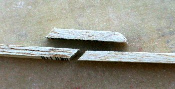
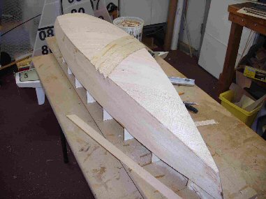
"John Fisher" is building Star 45's. He has provided a series of photographs taken as he builds the model from scratch.
These are posted to the blog along with his notes to help builders assemble the Star 45.

In the following posts you will find comments, notes. and his photographs

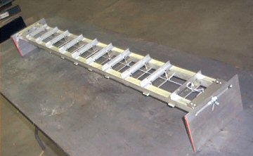
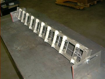
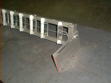
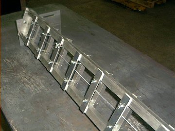
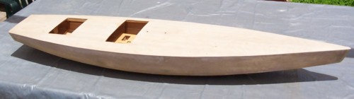
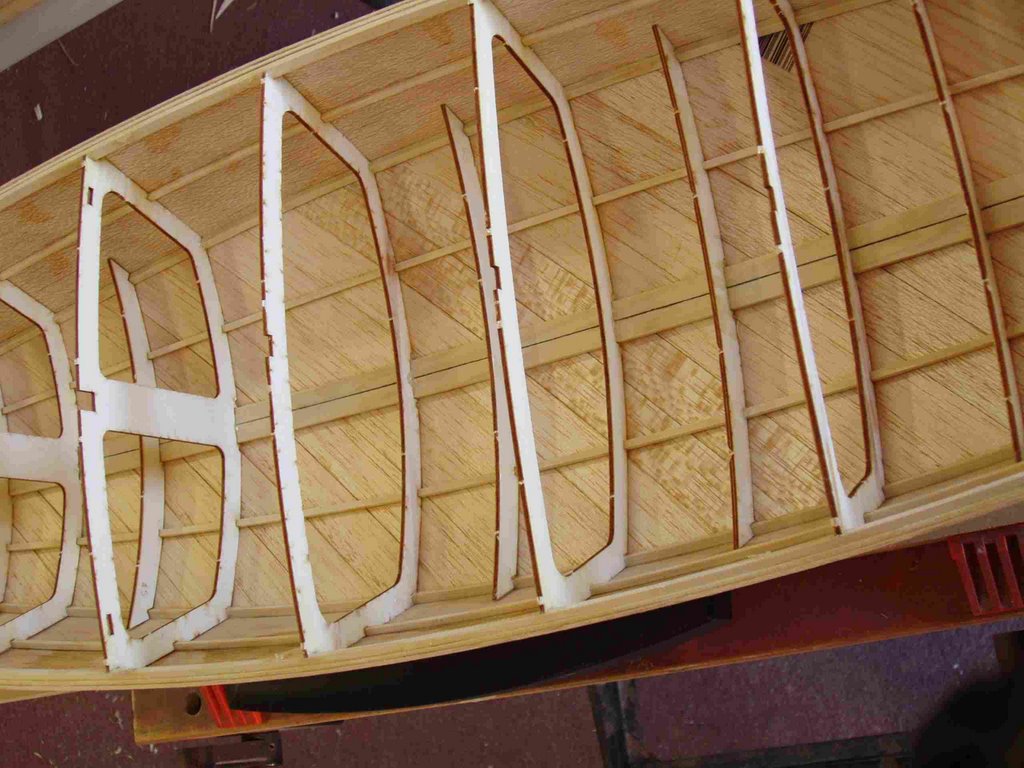
Photo's showing the building board and the first couple of steps for putting the frames together.
Building board is 3" wide 3/4" MDF that is glued/screwed together.

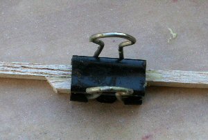
The notched balsa template is glued to the building board using a straight edge. Use a staight edge to make sure it stays straight.

S45 Construction: a cradle for the hull of wooden Star 45

From Star45 Yahoo Group - Message:
New use for John's Lasercut Frames-"Cradle Making":

Phil Geren needed a cradle for the hull of my woodie Star 45 under construction, to hold the hull while he fair the gunnels to the frames in preparation for installation of the deck and while designing and installing the controls (keel is not on yet).

Well, the easiest way to make a perfect cradle is by using the holes (which are left in the John Fisher lasercut frame sheets after removal of the lasercut frames, to trace the exact shapes of the outsides of frames 2, 4, 6, 8, and 10 onto 3/8' thick plywood. Allow for the thickness of planking and carpeting by drawing a second trace for each frame so that the hole for the hull is 3/8' bigger everywhere than the frame.

Then cut out each second trace as the inside of a frame for a cradle. Mount the cradle frames on a 2'X4' piece of particle board, using the spacing of the balsa template included in the frames kit, and using a try square to get them vertical, and making sure that they are all on the same longitudinal center and all parallel.

Then hot glue 1' wide strips of carpeting to the insides of the cradle frames. Voila! A perfect hull cradle.

Best,
Phil Geren"


Star45 : Message: The Perfect Cradle: "

Here are the hull cradle fotos I promised you.

Your shadow invention is so useful. The holes left in the plywood sheets after punching out the frames were used as templates to draw perfect frames for a cradle to hold the hull for completion of the construction (before keel installation).

Thanks so much!
Best regards,
Phil Geren"

Sailing Model, AMYA Star45 Class | Rudder

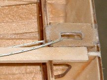
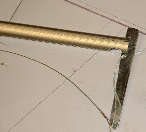
AMYA Star 45 Class Rules, 2006, Rudder

6.1 Rudders may be constructed of wood, fiberglass, plastic, plastic laminates or metal. The exact shape is not specified, but they may not exceed 4 1/2 inches at the hull (fore and aft) 3 inches at the bottom, (fore and aft); and may not project more than 7 inches below the hull when measured at the post..

S45 Construction | hull: double diagonal planking


From: "John Fisher"

Here are some photo's of Sherwood Jones Star 45 with double diagonal bottom planking. He used two layers of 1/16 planking. The planks are 1" wide. He then covered it with 1 ½oz glass. Weight is about the same as mine with the 1/16 longitudinal planks and two layers of 3.2 oz glass. Just goes to show that there are multiple ways to solve a problem.


John

Star 45 Construction Planking with edge glueing

[Star45] Update on planking bottom with edge glueing.

John Fisher is ready { 4/19/2007 } to glass his latest boat and is sharing how he planked it. His dad built a ply sided, cedar planked star using titebond II and it came out pretty light and stiff. With this information I started to build another hull using the same materials. He felt that edge gluing the planks added a lot of the strength to his boat. John didn't want to glue in extra wood to hold the pins to keep the planks in place for the glue to dry, so I combined two methods of planking. John liked the quickness of planking with CA and kicker, but it lacked stiffness when sanding the bottom before glassing. So he decided to edge glue the planks and then tack them in place to the frames with CA.

In this photo you can see where John put drops of CA on the planks. The wood is slightly darker.


It worked well. John has an edge glued bottom and he was able to plank it in one evening. To do this John first spray the frames with kicker, then apply titebond III to the edge of the planks. He then would hold the plank in place, tight against the previous plank, and apply a drop of CA to each frame to hold it in place. It did not matter where John started, bow, stern, or middle, but do make sure the CA has set up before moving to the next frame. Once the whole plank was in place he came back and wiped off the extra titebond. To fair the bottom to the sides he used a $10, 6" plane from home depot set at .010" depth of cut. It quickly removed the cedar and a little sanding finished the job.

John had one plank that was too thin that he had to remove, it was harder than expected. He had the use quite a bit of force to break the glue joint at each frame, so he is confident that this method is strong. John will also use this for balsa planked bottoms.

In photo # 10 you can see the stern still needs to be trimmed and sanded. John will probably use a saw to trim in close and then sand to fair it.

Sailing Model, AMYA Star45 Class | interior work, radio, sail controls, servos, mast support

Radio Board stringers between bulkheads

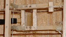
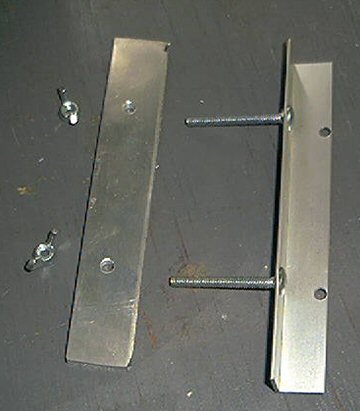
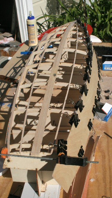
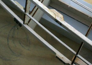
(Note the method of keel support using these stringers)
radiobd_1sml.2.jpg


Radio Board
radiobd_2sml.1.jpg


Rudder Servo
servo_sml.2.jpg


Mast support (inside hull)


internal mast support

Star 45 "Mainwaring keel and bulb" on an old S45

S45 Construction | John Fisher -- keel tubes

Photo sequence showing how John Fisher made his keel tubes. He was mounting a keel from CPM (David Ramos) with longer keel bolts so they will go through the deck when finished. He coated the brass rod with carnuba wax as a mold release.


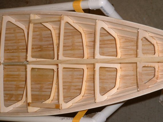
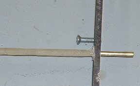
To align the keel tubes John drills the holes in the center of the boat, this is easy to find since it is simply the middle of the king plank and the middle of the two keel planks. Then to align them so they are straight he placed a metal ruler along the two keel bolts or if a flat plate along the plate. Then look at where the end meets the transom. It should be off center by half the amount as the bolts/keel are thick.

John does this on both sides to make sure it is centered. Once the bottom is aligned he tacks it in place with CA, then verify the alignment at the deck the same way.


Star 45 Keel fins building options, Star45

{Rule7.2}
Keel fins may be solid or hollow and constructed of reinforced plastic, plastic laminates, fiberglass, wood or metal. (Note: Strength and integrity of the keel fins must be maintained whether built solid or hollow.) Keel fin shape is not specified but must follow the general shapes outlined on the reference drawing. However, keels will not be less than 6 inches nor more than 8 inches long (Fore and Aft) at the keel/hull junction, nor less than 4 inches nor more than 6 inches long (Fore and Aft) at the keel/ballast bulb junction.

--
The Mainwaring Keel shape is a fine choice!
--

John Fisher suggests:

The quickest and easiest way to make them if you have access to a metal band saw is to draw the keel in CAD, then print it out. Glue that to a sheet of 3/32 aluminum with 3m77 and cut it to shape.

You could also do the same thing with sheets of plywood and layer it to achive a airfoil shape. Each layer should be smaller than the last and then sand to blend the layers. Could also make a good cad project.

Another way is to cut the shape in two pcs of 1/16 ply, then tape the edges together. Insert a couple of threaded rods between the two sheets for attachment. Then fill with epoxy and microballoons. Using this method you should also glass the outside for additional stiffness. There are photo's of making a rudder like this on the blog site.

--

S45 radio install

A Drum style model sail winch


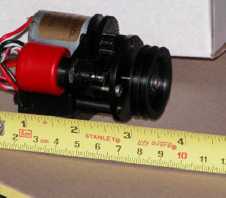
photo's courtesy of "Larry Ludwig" at www.LudwigRCYachts.com, Ludwig Mfg.


==

From: "Stephen Pratt" :
"On the North Coast (Ohio), are using HiTec HS-725 or HS-785 Winches. Bob Luther developed a mechanism to work an endless loop system of sail control. Fits inside the Star 45 with plenty room to spare."

S45 Model Boat construction | Sail Control Units

installing the radio tray for an under deck winch, jib tweaker, and rudder servo. From John Fisher:


The radio tray is 1/16 ply backed up with 1/8 X 3/8 spruce or basswood. Note the glassing at the ends. This adds a lot of strength to the joint and John highly recommend adding it. John uses 1" wide glass tape cut in half, then sprayed with 3M77 so it will stay in place for gluing. Then a dab of your favorite epoxy and you are done.


sheet through deck mount.


jib tweaker turn around. The part is a 180 deg sheet lead from great basin.


See also http://woodstar45.blogspot.com/2006/10/blog-post_116031550255831231.html
--
From: David Ramos To: Star45@yahoogroups.com
Sent: Fri, 14 Nov 2008 10:23 am
The following photos show my set up for a drum servo and jib tweaker.

--
Note:
One major advantage of building from a fiberglass hull is the open space inside the hull. David Ramos offers workmanship second to none.

Dave Mainwaring
--
http://www.rcyachts.com/STAR45/P1010084.JPG


http://www.rcyachts.com/STAR45/P1010082.JPG


Main sheet is 2:1 and jib sheet is 1:1

Hope this helps
David Ramos
Chesapeake Performance Models
227 Main Street
Stevensville, MD 21666
david@rcyachts.com
www.rcyachts.com