Search This Blog

12/31/2008

Now come the questions... ;-) 12.28.08

"tony.crouch"

I'm going to order a CPM keel bulb and I'm wondering how it will attach to the plywood Mainwaring keel. I don't want to start sanding and fairing the keel until I know how that's going to work.
--
"Dave Mainwaring"

Here is how I mounted an aluminum fin to the hull so that it could be removed (interchangeable keels) ths method should also work for wooden fins.

http://star-45.blogspot.com/2006/08/s45-construction-keel-trunk-alignment.html#links

Dave Mainwaring

--
"J Fisher"

Here is how I attach the bulb. First I mark the center of gravity of the bulb. This is done by balancing the bulb on a small PC of rod. Once I have the CG located, I float the boat with the lead on top of the deck. Then adjust the bulb location until the transom is just out of the water. The bulb CG can then be measured in reference to the keel bolts. The fin is already to max depth so it should go through to the bottom of the bulb when fitted. Also the bulb seems to have an upward tip already so I just have it sit on the table for correct tilt with the fin sitting vertical.

I then trim the hole in the bulb and the fin until the bulb ends up in the right spot. The fin is easier to cut than the bulb. I use a chisel and file to enlarge the hole in the bulb. The fin is pretty much completed by this time, i.e. Shaped and glassed. Once everything fits correctly, I place the fin into the bulb and drill a hole for the roll pin or pins depending on the fin location (see note below). I install the pin, then use something like steel epoxy to fill the bottom of the hole. It is a two part epoxy clay that you buy in a roll, cut to length then mash together to cure. I use the under water version which is white. Once the bottom of the bulb is closed off, I pour in epoxy from the top to full any voids and seal everything. Then I fair the keel to the bulb with more of the epoxy clay. Then sand and paint.

To prep the bulb I use my orbital sander to sand down the bulb and remove any imperfections. This goes really fast with the sander. Please take appropriate caution when dealing with lead, wear a respirator and wash hands before eating. Once it is mounted I coat with epoxy then sand smooth.

Since I put my fins farther aft than the current plan location my bulbs end up sticking pretty far forward of the fin. About 1" further aft than the plans. I used the same location as Scott Rowland does in his tuning guide. This location seems to work well for heavy air, but does require you to steer the boat down wind. It also adds some lee helm in the really light stuff requiring the rig to be moved well aft to balance. With traveling to regatta's you never know what the wind will be like so I need a good all around boat. I would make a different choice if I always sailed in light conditions.

John
--

Philgeren@...
phil_geren

I just want to add a couple of things to John Fisher's great answer:
When drilling lead, use a generous amount of cutting fluid (the kind used for lubricating dies when cutting threads in pipe). This will make the drilling easy and prevent the bit from binding in the lead.
Should you waterproof inside the hull? YES. Even the dryest boats get some water inside, and it will be absorbed by the planking if the planking is not waterproofed. You want to be able to drain any water that gets inside, not have it increase the weight of the boat. Two coats of epoxy are recommended on all interior wood surfaces not otherwise waterproofed.
--
"J Fisher"

When I work with the lead bulbs I try not to do anything that requires machining or drilling the lead. The CPM bulb already has a hole for the roll pins and the fin, so you don't have to drill any holes in the lead, just the keel. Lead is so soft that it quickly gums up any cutting tool. Using coolant (water) or cutting oil (plain cooking oil works well) helps, but is messy. With this in mind the last two bulbs I used had the slot opened up with a combination file/chisel I got at Lowes. This was not a quick process but it did work pretty well. A plain wood rasp would probably also work fine. I have also heard that a sherform works well for shaping lead.
--

Philgeren@...
phil_geren

I recently had to change the shape of the keel slot in a lead bulb made in two halves by Phil Runquist, a beautiful dolphin shaped bulb.

The best thing I've found for cutting lead is a common woodworking chisel and a mallet. Lead shaves as easily as wood, and you have total control of the cut by the angle at which you hold the tool. Narrow chisels are easier to use than wide ones. It is best if you build a little jig to hold the bulb stationary while you pound on the chisel.

I mixed the lead shavings with JB Weld (epoxy containing iron powder) and put them back into areas of the slot that needed closing up.

If I have to sand lead, I do it under water, by hand, using wet-or-dry sandpaper, wearing rubber gloves.

The water keeps the lead from dusting and contains it for collection or disposal, keeping it out of your body.

It is important to be meticulous about protecting yourself from lead contamination.
--

Ed Hilton

I am planning on casting my own keel. How much do most of the keels weigh for these boats.
--

Larry Ludwig

I would just want to remind all of you guys that are working with lead that it is extremely toxic, and should never be handled without gloves. You should avoid any skin contact with lead period. Also, if you are planning on casting lead, you should do it OUTSIDE and I mean WAY outside, where the fumes are going away from you. If you can smell it, it can poison you, that is the simple rule. Obviously away from children/pets. When I cast lead I have two large shop fans that I use behind me to make certain that the fumes are moving away. I simply cannot stress strongly enough that this stuff, as with certain paints, and cutting carbon fiber can and will reduce your lifespan, or make what you have left miserable.
--

Ed Hilton

In planning to cast my own blub, How long are your blubs and what is the diameter?

--
"Dave Mainwaring"

Here is a earlier post on casting bulbs:

Wednesday, July 05, 2006

Star 45 R/C model sail boat , making a keel bulb mold and Castings

From Jim Adams:

I made a plug from balsa and finished it to a smooth finish second I used two aluminum pans (the kind that you throw away) I filled the first one with plaster took the bulb (well waxed) and placed it in the plaster half way in I used two pins through the center to hold it down. let that dry then pull out the plug next put thin saran wrap over the mold and place the plug back in the hole.

Now comes the fun part I used rubber bands to hold the plug in place (remember I had two pins that extend past the mold walls) next fill the second pan with plaster and lay the first on top it is kind of messy but it works. When the second half dries (about two hours) pull them apart. You will need to plug the holes at the ends on the sides and create small air path upward in the and a spur (looks like a funnel when you are done this needs to be big enough to pour in the led) at the end.

Billie Geisler's comments regarding "Keel Bulbs 2006 August 1:

I advise against using tire weights for ballast bulbs, because the tire weights seem to be some sort of alloy, and not pure lead. The markings on the weights are a good indicator, as different physically sized weights have the same ounce values stamped on them. So, if you use tire weights, you will have a physically larger bulb to achieve the necessary weight, thus more wetted surface friction, resistance through the water.

I go to the plumbing supply store to buy lead. This lead is much denser than tire weights. The lead comes in various shapes, some like hocky pucks, and some like Snickers bars. The Snickers bars fit into my lead pot better.

Incidentally, fishing supply stores sometimes carry electric lead pots, along with fishing weight molds. Good use for your tire weights. I was lucky enough to find a lead pot at a garage sale, sold by a rifleman who no longer cast his own bullets.

Consider mounting the ballast bulb on the keel fin at an angle, about 1 to 3 degrees up at the front. You can find info on performance of this arrangement on some IOM sites. It makes a substantial difference in boat speed on an IOM.

I cast my bulbs in two plaster of paris molds. One mold for the outer cheeks of the bulb(split fore and aft), and one for a center peice, to go between the cheeks. The thin (about 1/8 inch thick) center peice can be easily cut for fitting the fin, and drilled for adjusting the weight. If I need filler, I mix buckshot with epoxy. I can rough sand the lead with a belt sander, with very course belt. The course belt doesn't fill with lead.

--
Terry Harmer


When I finish a lead bulb I wait until it is on the fin, then I:

Scrape off the rough edges with a knife.
Wipe it thoroughly with alcohol.
Pad the fin and put it in a vise with the small end of the bulb pointing down.
Put a bucket with water right underneath the bulb.
Mix a batch of epoxy and just drip it over the top of the bulb until the bulb is covered.
(The excess epoxy drips off the small end and into the bucket, jar, or whatever.
When cured, I repeat.
When done, you have an almost perfect coating over the bulb.

Now just fill any minor dips, sand and paint.

This ensures that I don't mess with the raw let much.
--

"J Fisher"

I would use around 8 lbs if you plan on sailing in heavy air. If you sail in light air, you can probably get away with a bulb down to 7lbs. I think the blackwells are all about 7.5 lbs. The latest CPM bulbs have been right about 8.5 lbs and the Skid-Do bulbs seemed to be right about 8 lbs.

With the top several boats in the last 2 nationals being well over the 12 lb minimum I don't think overall boat weight is super critical. I do think that having enough lead is more critical than the overall boat weight.

--
"Dave Mainwaring"
Someone asked about shapes an sizes.

I like keels that resemble in some manner the "Scheel Keel". Flat bottoms help fight heeling. My version was based on my sailing in waters with lilies and pond grass that snagged torpedo shaped bulbs. I liked being able to back away and have the crap slide off the keel.

http://photos1.blogger.com/blogger/5587/620/400/Sirius%2045%2006.jpg


http://photos1.blogger.com/blogger/5587/620/400/Sirius%2045%2002.jpg
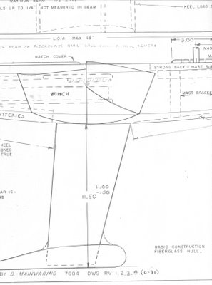


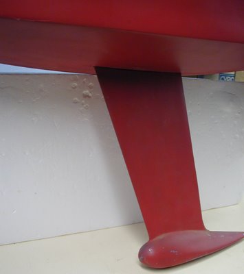
Here is a photo of the original Mainwaring Keel ad Mainwaring Bulb

http://photos1.blogger.com/x/blogger/5587/620/400/353321/Sirius45Keel.jpg


12/01/2008

Pat's Hacks, servo motor conversions

Thank Pat Matthews for sharing the following post on servo hacks!

Servos are wonderful little devices! Not only do they provide an inexpensive way to activate mechanical linkages through radio control, but they can be hacked to provide inexpensive drive units for small boats and cars with their self-contained motors and electronic speed controls (ESC's), and they can serve as part of a simple on/off power control switch.


Basic servos can be found for less than $10

A servo is a little gear-motor, ESC, and a position sensing device in one package. Rip the guts out of the case, and you'll have:
a) A lead from the Rx… it carries +5 volts, ground, and a signal wire.
b) A circuit board.
c) A small 5v motor, which may be soldered directly to the circuit board.
d) A pile of gears connecting the motor to the servo output. Bin these.
e) A potentiometer (pot, or variable resistor) connected to the circuit board with 3 leads, and mechanically connected to the servo output.

Step 1: A few screws loose, and things start to open up.Step 2: Pressing on the two shafts popped the board out of the case. Don't pry directly on the board.
Step 3: Using desoldering braid to wick off the solder, makes it easier to pull off the motor.
Loose parts.

Hack 1: Going Pot Free

First trick in hacking a servo: Disconnect the pot from the servo output. Normally, as the pot moves with the servo output, it produces a varying voltage which is read by the circuit board, telling the servo that the output has moved to the desired position (or not). See Schematic 1. When you disconnect this little knob from the gear train and the servo output, leaving it in it's centered position, and then command servo movement at the radio, the circuit board never detects any movement, and thus keeps telling the motor to run.
So now center the stick, servo is happy, goes nowhere; forward stick, and the motor kicks in and just keeps buzzing; reverse stick, ditto the other way. You'll want to put a drop of glue on the pot to keep it from drifting.

Hack 1a: If the Pot itself doesn't suit you, you can replace it with a pair of 2.2k ohm resistors- both tied to the center tap's lead, opposite ends of the resistors to the pot's "outer" leads.


Another nice feature- most servos have a soft start, which means that a little bit of stick will give part throttle… other than that, it's pretty much off/on.


Hack 2: Motor Swapping

Next hack: The little motors that comes with servos may not suit you… they have tiny little short shafts. Any small 6v toy motor will do instead, as long as you don't load it heavily- the servo's ESC isn't designed to deliver much current! If the motor is connected to the circuit board with wires, no problem to swap them. If the motor is soldered directly to the board, you'll need to work a little more carefully. You can get "solder braid" from Radio Shack- braided copper wire that you heat with a soldering iron while pressing onto the board's soldered joint. The braid sucks up the solder, and you can pull the motor loose much more easily.


If you decide to keep the servo motor, no problem. You can leave the motor on the board- that's what I did on my plastic landing craft. And you can get tiny little plastic u-joints to press onto various miniature shaft sizes, metric and English, from Northwest Shortlines- catalog page at http://www.nwsl.com/Catalog/cat-UJoint.pdf


Servo motor still attached to board. Motor can is pressed into plastic structure. Twin drive in landing craft.
Servo motor set in Revell Trawler Close-up of NWSL U-Joint on servo motor's 1.5mm shaft. "Horn" is sized for 1/16" prop shaft, which is only slightly larger than 1.5mm.


Pat's site: http://www.geocities.com/patsmodels/servo/

Pat's Hacks, servo motor conversions

Thank Pat Matthews for sharing the following post on servo hacks!

Servos are wonderful little devices! Not only do they provide an inexpensive way to activate mechanical linkages through radio control, but they can be hacked to provide inexpensive drive units for small boats and cars with their self-contained motors and electronic speed controls (ESC's), and they can serve as part of a simple on/off power control switch.


Basic servos can be found for less than $10

A servo is a little gear-motor, ESC, and a position sensing device in one package. Rip the guts out of the case, and you'll have:
a) A lead from the Rx… it carries +5 volts, ground, and a signal wire.
b) A circuit board.
c) A small 5v motor, which may be soldered directly to the circuit board.
d) A pile of gears connecting the motor to the servo output. Bin these.
e) A potentiometer (pot, or variable resistor) connected to the circuit board with 3 leads, and mechanically connected to the servo output.


Step 1: A few screws loose, and things start to open up.

Step 2: Pressing on the two shafts popped the board out of the case. Don't pry directly on the board.

Step 3: Using desoldering braid to wick off the solder, makes it easier to pull off the motor.
Loose parts.

Hack 1: Going Pot Free

First trick in hacking a servo: Disconnect the pot from the servo output. Normally, as the pot moves with the servo output, it produces a varying voltage which is read by the circuit board, telling the servo that the output has moved to the desired position (or not). See Schematic 1. When you disconnect this little knob from the gear train and the servo output, leaving it in it's centered position, and then command servo movement at the radio, the circuit board never detects any movement, and thus keeps telling the motor to run.
So now center the stick, servo is happy, goes nowhere; forward stick, and the motor kicks in and just keeps buzzing; reverse stick, ditto the other way. You'll want to put a drop of glue on the pot to keep it from drifting.

Hack 1a: If the Pot itself doesn't suit you, you can replace it with a pair of 2.2k ohm resistors- both tied to the center tap's lead, opposite ends of the resistors to the pot's "outer" leads.


Another nice feature- most servos have a soft start, which means that a little bit of stick will give part throttle… other than that, it's pretty much off/on.


Hack 2: Motor Swapping

Next hack: The little motors that comes with servos may not suit you… they have tiny little short shafts. Any small 6v toy motor will do instead, as long as you don't load it heavily- the servo's ESC isn't designed to deliver much current! If the motor is connected to the circuit board with wires, no problem to swap them. If the motor is soldered directly to the board, you'll need to work a little more carefully. You can get "solder braid" from Radio Shack- braided copper wire that you heat with a soldering iron while pressing onto the board's soldered joint. The braid sucks up the solder, and you can pull the motor loose much more easily.


If you decide to keep the servo motor, no problem. You can leave the motor on the board- that's what I did on my plastic landing craft. And you can get tiny little plastic u-joints to press onto various miniature shaft sizes, metric and English, from Northwest Shortlines- catalog page at http://www.nwsl.com/Catalog/cat-UJoint.pdf


Servo motor still attached to board. Motor can is pressed into plastic structure. Twin drive in landing craft.
Servo motor set in Revell Trawler Close-up of NWSL U-Joint on servo motor's 1.5mm shaft. "Horn" is sized for 1/16" prop shaft, which is only slightly larger than 1.5mm.


Pat'web site http://www.geocities.com/patsmodels/servo/

11/15/2008

Drum Servo with Jib Tweaker from Dave Ramos

From: David Ramos To: Star45@yahoogroups.com
Sent: Fri, 14 Nov 2008 10:23 am
The following photos show my set up for a drum servo and jib tweaker.

http://www.rcyachts.com/STAR45/P1010084.JPG


http://www.rcyachts.com/STAR45/P1010082.JPG


Main sheet is 2:1 and jib sheet is 1:1

Hope this helps
David Ramos
Chesapeake Performance Models
227 Main Street
Stevensville, MD 21666
david@rcyachts.com
www.rcyachts.com

11/13/2008

The Star 45 R/C Model Sail Boat

The Star 45 R/C Model Sail Boat - Builders Journal

Construction photographs, articles about the Star 45. -- Join the AMYA STAR45 Class discussion group http://groups.yahoo.com/group/Star45/ -- Read about How To Build A Wooden Star45 R/C Sailing Model! Browse http://woodstar45.blogspot.com/ Based on the International Star Boat this semi-scale Star45 can be scratch built by novice or seasoned skipper. Easily radio controlled and large enough to see out on the water this is a classic model model built by hobbyists for over thirty years!

11/06/2008

1/16 and 1/8 plywood

Boulter Plywood in Summerville, MA carries ( 1/16 ?) and 1/8 okoume plywood for a fraction of the cost of the on line hobby stores.


They also carry Baltic Birch plywood: 1/16'' and 1/8''

http://www.boulterplywood.com
toll free at 888 - 9 LUMBER. (888) - 958 - 6237
or Email: chris@boulterplywood.com

--

Okoume Plywood Information:

1.Face / back: okoume Core: poplar, hardwood, pine ,

2.Size: 1,220 x 2,440mm, 1,250mm x 2,500mm, 915 x 1,830mm or as requested

3.Thickness: 3.5mm-30mm

4.Glue: WBP, MR, E1, E2

--

Wood Properties of Okoume from
http://www.connectedlines.com/wood/wood47.htm

Okoume Alternative Name 1
Gaboon

Okoume Available as Veneer
Yes

Okoume Bending Strength
Moderate

Okoume Blunting of Tool Blades
Moderate to Severe

Okoume Botanical Name
Aucoumea klaineana

Okoume Carving
Average to somewhat difficult to carve

Okoume Clear Finish or Varnish
Fair

Okoume Color of Wood
Pink Brown

Okoume Density
Low

Okoume Drilling
Fair or Satisfactory

Okoume Gluing
Good

Okoume Grain
Mostly Straight

Okoume Hand Tooling
Average

Okoume Hardness
Soft, easy to dent

Okoume Hardwood or Softwood
Hardwood

Okoume Harmful Properties
Non Toxic

Okoume Mortising
Fair or satisfactory

Okoume Nail Holding
Good- Nails are fairly difficult to pull out

Okoume Nailing
Fair - may require pre-drilled pilot hole especially near ends

Okoume Natural Durability
Non-durable

Okoume Polishing
Good

Okoume Sanding
Fair or satisfactory

Okoume Sawing
Moderate cutting resistance

Okoume Screw Holding
Good - Fairly difficult to remove screws

Okoume Screwing
Fair - May require pre-drilled pilot holes especially near ends

Okoume Size of Pores
Insufficient Data Available

Okoume Staining
Fair - May stain unevenly or change colors

Okoume Steam Bending
Poor

Okoume Stiffness
Low

Okoume Surface Preparation for Finishing
No

Okoume Texture of the Wood
Intermediate

Okoume Weight
Light

Okoume Wood Defects
Check (or split,) warp

11/01/2008

Dave's R/C Friendship Sloop model Florida


Another of Dave Mainwaring's, Friendship Sloops:
Florida,
R/C fiberglass, built in 1970

R/C model Friendship Sloop


Another of Dave Mainwaring's R/C Friendship Sloops,
medium size models make nice display models
However they are tender on windy days.

Pemiquid style Friendship Sloop R/C ,model


Billy Hogan with his Friendship Sloop.
January 2005
kit was circa 1971 from Dave Mainwaring
They make a beautiful R/C sailing model

Friendship Sloop - Pemiquid


Billy Hogan with his Friendship Sloop.
January 2005
kit was circa 1971 from Dave Mainwaring
They make a beautiful R/C sailing model

Top view 42in Jonesport Lobster Boat model


42in_lb_model_06.jpg
Posted by Hello

Jonesport model under construction, , 42 inch glass hull


42in_lb_model_10.jpg
Posted by target='ext'>Hello

42in_lb_model_03.jpg
Posted by Hello

Dave Mainwaring, 42 inch model under construction

Fibre Glast Developments _ Estimating Materials

The Fundamentals of Fiberglass - Fibre Glast Developments: "Worksheet For Estimating Materials

1) Begin by calculating the surface area of the project. Estimate irregular shapes by measuring the approximate sized rectangles necessary to contain the tapered areas. Multiply the length times the width for each rectangle, and then add all of individual rectangles together to get the total surface area of the part. If the calculation is in square feet, divide by 9 to get square yards.

2) Make a list of each type of reinforcement being considered for the lamination. Multiply the square yards calculated above times the ounce weight of the fabric. This is the total weight of one layer of that material. It is also the amount of resin required to saturate it. When this is known for two or three different types of materials, it is possible to calculate the weight and cost of a laminate constructed from any combination of these fabrics. To convert the ounce weight to pounds, divide by 16. Those inexperienced in saturating fiberglass tend to use far too much resin. A well saturated laminate is uniformly translucent, without milky appearing dry spots, but for the sake of weight and cost, has little excess resin in it."

The Fundamentals of Fiberglass - Fibre Glass Developments

The Fundamentals of Fiberglass - Fibre Glass Developments: "Estimating Material Weights And Cost

Accurate material estimates are necessary for two reasons.First, they obviously are needed for proper ordering, material stocking, and bidding of projects. More importantly though, estimates offer the opportunity to calculate the weight or cost of the part using a variety of laminating schedules before beginning to build.

Unlike estimating coverage when painting, resin usage will vary depending on the type of reinforcement being used. The heavier the fabric, the more resin it will take to wet it out. A good hand laminate consists of about 50% fabric and 50% resin by weight. For example, if an application requires 3 sq yds of a 4 oz/sq yd fabric (total fabric weight = 12 ounces), 12 oz of resin will also be needed. However, if 3 yards of 10 oz/sq yd fabric is chosen (total fabric weight = 30 ounces), 30 oz. of resin will be needed.

Glass mat requires a minimum of 2 ounces of resin for each ounce of mat. Therefore, it the application calls for 20 sq feet of 1-1/2 oz/sq ft mat, it will require a minimum of 60 ounces of resin. Remember that mat is specified in ounces per square foot, where fabrics are specified in ounces per square yard. 1-1/2 oz/ sq ft chopped mat actually weighs 13.5 oz/ sq yd!

Since there are so many possible combinations of materials, one should calculate the weight and cost of a single layer using a variety of reinforcements. These can then be added or subtracted form the theoretical laminate until the design properties are achieved."

10/16/2008

Thinning Epoxy

Thinning West System Epoxy by Brian Knight
http://www.seqair.com/skunkworks/Glues/WestSystem/Thinning/Thinning.html

"This article appeared in the Fall 1999 issue of Epoxyworks, published by Gougeon Brothers, manufacturers of the West System epoxies." Brian Knight thanks Gougeon for permission to publish this in the December 1999 Falco Builders Letter. "

Here are key excerpts for your review and discussion:

"With wood, the best method of thinning epoxy with heat is to warm the wood and have the resin and hardener at room temperature. Mix the components and apply the mixture to the warm wood surface. Remove the heat source just before the epoxy is applied. When the epoxy mixture comes in contact with the warm wood, it gets warm and its viscosity becomes lower. As the temperature of the wood falls, the thin epoxy is drawn in deeply before it begins to gel. By heating the substrate instead of the components, you get the best of both worlds-low viscosity epoxy on the work surface and longer working time in the mixing pot."

Thinning epoxy with solvent
Adding solvent is a quick, simple method of thinning epoxy, but unlike using heat to thin it, the strength and moisture resistance of the cured epoxy are drastically affected. Below are some of the effects adding solvent has on West System epoxy. While there are a large number of chemicals available to thin epoxy, we selected acetone, lacquer thinner and denatured alcohol for this discussion because they are commonly available and do a good job of reducing viscosity. Additionally, these solvents evaporate quickly and are less likely to be trapped in the cured epoxy-an important characteristic. For a variety of reasons, fast evaporating lacquer thinner appears to be more appropriate for thinning purposes than acetone or alcohol.

10/15/2008

So you want to build a sailing model

Find plans for a sailing model, buy or find on-line.

Join a model boat forum for advice.

Buy or borrow books on boat building.

Decide on type of planking and wood to be used to build the model.

Set aside a work space for building.

Review the bill of materials need to build the model and buy the materials.

Order deck and mast fittings.

Order mast (if you are buying the mast) and order sails (or sail material).

Choose the radio system, buy a sail control unit, Order keel bulb or get advice and discuss issues of building your own.

While the hull is under construction build:

Keel fin and ballast bulb

Rudder assembly

Make or assemble spars ( mast and booms)

Build cradle to hold boat under construction and when finished.

Test Radio System and sail control unit

After hull is planked:

Install keel trunk or make provisions for mounting keel.

Install radio and sail control unit, Then remove while construction continues.

Construct deck and hatches

Install/mount deck fittings

Test access to radio and sail control inside the hull.

Provide a exit guide for radio antenna so it can be attached to mast or stays.

Install power switch for turning off batteries

Test mount keel

Paint hull, rudder and keel

Assemble hull, rudder and keel

Set up mast and boom.

Install radio controls.

Check running rigging.

Attach Sails

dry sail model

--

Sail
Display
Storage

Model Sailboat Plans on line


Most browsers will allow you to right click and open the jpg images. You can then save them to your machine.

This set of plans are based on drawing from John Fisher 2006. John may have new and updated drawings available. Check with http://groups.yahoo.com/search?query=star45 membership required.

I want to thank J. Herrmann, www.graphicLanguageOnline.com, for his assistance in converting pdf's to jpg drawing, adding color to the templates and adding the grid to the final images

You can print these drawing to many different sizes.They are not necessarily to scale.

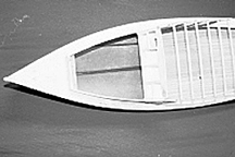
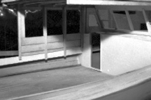
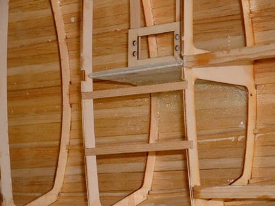
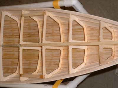
Inside a R/C sailing model hull

John Fisher photographer and builder!
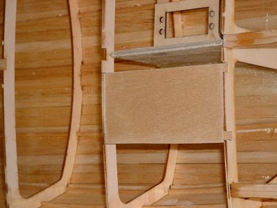
Radio Board stringers between bulkheads
(Note the method of keel support using these stringers)
radiobd_1sml.2.jpg


Radio Board
radiobd_2sml.1.jpg


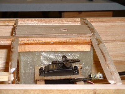
Rudder Servo
servo_sml.2.jpg


Mast support (inside hull)


internal mast support

S45 sail boat Rigging Bill of Material from John Fisher

To:Star45@yahoogroups.com
From: 'J Fisher'jfisher@wildblue.net
Sender: Star45@yahoogroups.com
Date: Wed, 3 Jan 2007 21:02:38 -0700 (Mountain Standard Time)
Subject: Re: [Star45] Deck rigging and such

Here is the list on the star 45 yahoo groups for rigging. I am using the following for my next couple of builds:
GBMY item #, description, qty, purpose
019, 3/8' alloy tube, 1, Jib boom
034, Hales single block, 2, main and jib sheets
146, tapered drain plug, 1, plug in transom
182, Z sheet hook, 2, sheet ends/boom attachment
202, large bowsie, 1, back stay/forestay with 80 lb Dacron, order small ones if using spektra
206, O-rings, 1, hold the Z hooks to the boom.
254, double block, 2, main sheet and jib sheet adjuster
255, sheet exit, 1, turning block for main sheet from under deck to above deck.
269, eye plate, 1, mounting for jib block.
272, 180 deg sheet lead, 1, turn around for jib tweaker
280, sheet hook, 1, hooks for backstay and fore stay.
282, tang, 1, attach lowers to mast.
907, rigging screw, 4 hooks, 2 packs, upper and lowers to the deck.

I also build my own chain plates, so I don't order them from GBMY. Don does carry them if you need them. I also like the Ludwig mast better than the bantock mast, so I ordered 8 foot masts cut to 69' from Larry Ludwig, the other 28' or so is the main boom. Last time I made all my own boom vang, mast fitting. This time I ordered them from Larry. You can use the bantock mast, boom, and fittings from GBMY as well. They are good stuff and I have them on my IOM.

The back stay crane is made from 1/16 (.063') aluminum that I bought at the local hobby shop.

John Fisher

---


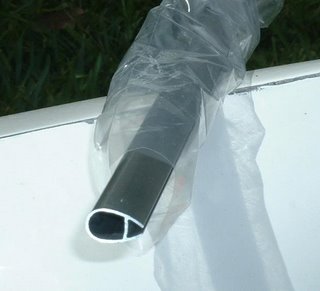
photo's courtesy of "Larry Ludwig" at www.LudwigRCYachts.com, Ludwig Mfg.